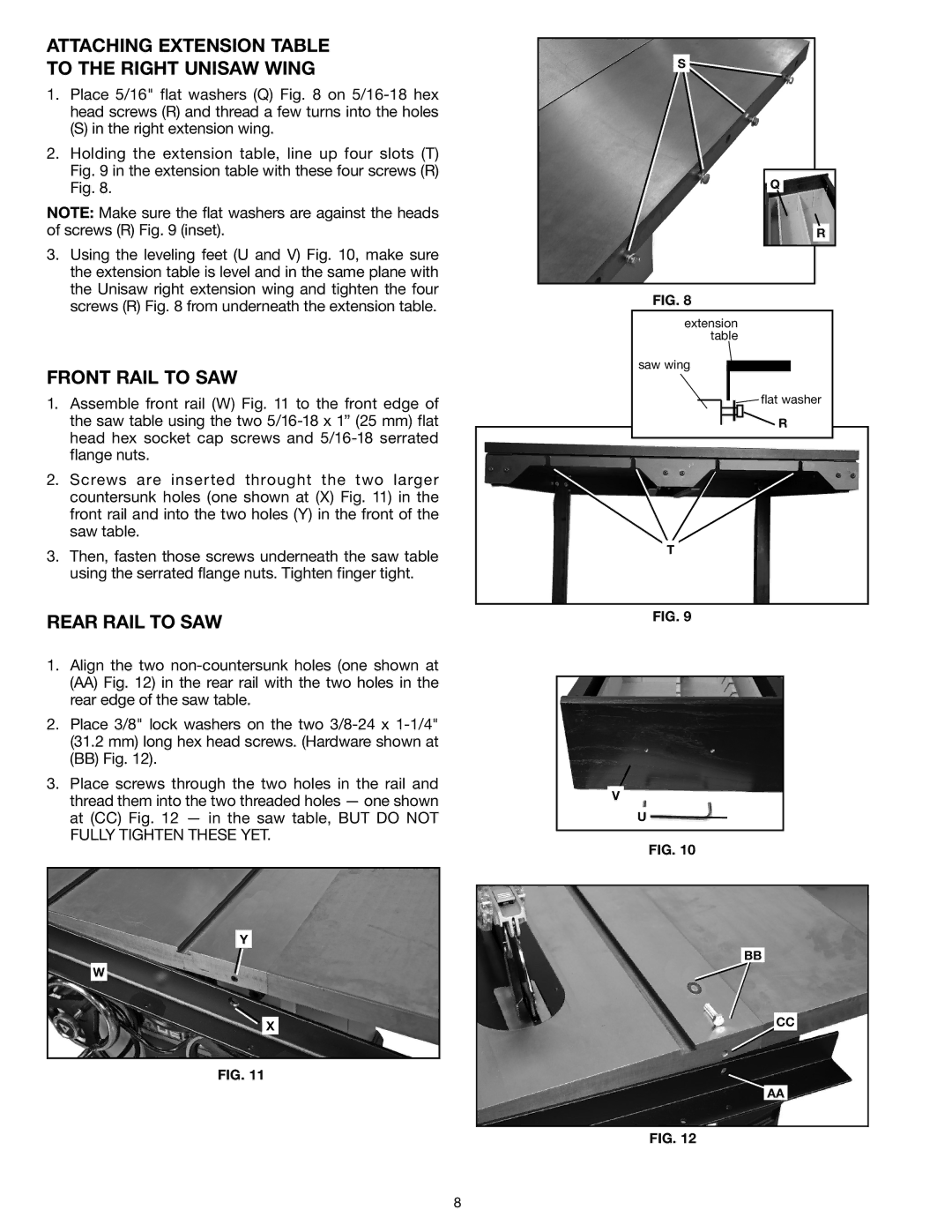
Attaching extension table to the right Unisaw wing
1.Place 5/16" flat washers (Q) Fig. 8 on
(S) in the right extension wing.
2.Holding the extension table, line up four slots (T) Fig. 9 in the extension table with these four screws (R)
Fig. 8.
NOTE: Make sure the flat washers are against the heads of screws (R) Fig. 9 (inset).
3.Using the leveling feet (U and V) Fig. 10, make sure the extension table is level and in the same plane with the Unisaw right extension wing and tighten the four screws (R) Fig. 8 from underneath the extension table.
FRONT RAIL TO SAW
1.Assemble front rail (W) Fig. 11 to the front edge of the saw table using the two
2.Screws are inserted throught the two larger countersunk holes (one shown at (X) Fig. 11) in the front rail and into the two holes (Y) in the front of the saw table.
3.Then, fasten those screws underneath the saw table using the serrated flange nuts. Tighten finger tight.
REAR RAIL TO SAW
1.Align the two
(AA)Fig. 12) in the rear rail with the two holes in the rear edge of the saw table.
2.Place 3/8" lock washers on the two
(31.2 mm) long hex head screws. (Hardware shown at
(BB)Fig. 12).
3.Place screws through the two holes in the rail and thread them into the two threaded holes — one shown at (CC) Fig. 12 — in the saw table, BUT DO NOT
FULLY TIGHTEN THESE YET.
Y
W
X
Fig. 11
S
Q
R
Fig. 8
extension table
saw wing
![]() flat washer
flat washer
R |
T |
Fig. 9
V
U
Fig. 10
BB
CC
AA
Fig. 12
8