Attaching RAILS TO EXTENSION Table
NOTE: Do the next steps in order presented. The extension table and main saw cast iron table must be level and flush to ensure smooth operation of your fence. To get the table level, it is important to attach the pieces in this order:
1.Front rail to the extension table.
2.Rear rail to the extension table.
3.Rear rail to the Unisaw. Though it is already attached, tightening this hardware firmly is the last step.
NOTE:
Attaching front rail to the extension table
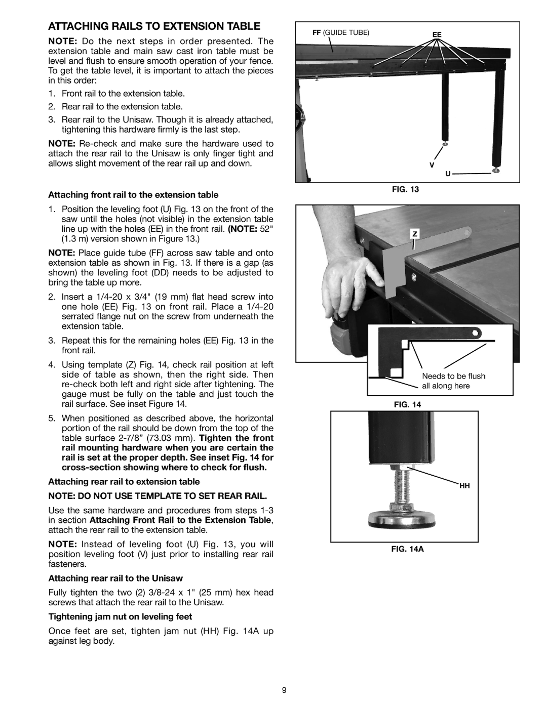
1.Position the leveling foot (U) Fig. 13 on the front of the saw until the holes (not visible) in the extension table line up with the holes (EE) in the front rail. (NOTE: 52" (1.3 m) version shown in Figure 13.)
NOTE: Place guide tube (FF) across saw table and onto extension table as shown in Fig. 13. If there is a gap (as shown) the leveling foot (DD) needs to be adjusted to bring the table up more.
2.Insert a
3.Repeat this for the remaining holes (EE) Fig. 13 in the front rail.
4.Using template (Z) Fig. 14, check rail position at left side of table as shown, then the right side. Then
5.When positioned as described above, the horizontal portion of the rail should be down from the top of the table surface
Attaching rear rail to extension table
NOTE: Do not use template to set rear rail.
Use the same hardware and procedures from steps
NOTE: Instead of leveling foot (U) Fig. 13, you will position leveling foot (V) just prior to installing rear rail fasteners.
Attaching rear rail to the Unisaw
Fully tighten the two (2)
Tightening jam nut on leveling feet
Once feet are set, tighten jam nut (HH) Fig. 14A up against leg body.
FF (GUIDE TUBE) | EE |
|
V
U
Fig. 13
Z
Needs to be flush |
all along here |
Fig. 14
HH
Fig. 14A
9