ADJUSTING THE FENCE TIGHTNESS
![]() To reduce the risk of injury, turn unit off and disconnect it from power source before installing and removing accessories, before adjusting or when making repairs. An accidental
To reduce the risk of injury, turn unit off and disconnect it from power source before installing and removing accessories, before adjusting or when making repairs. An accidental
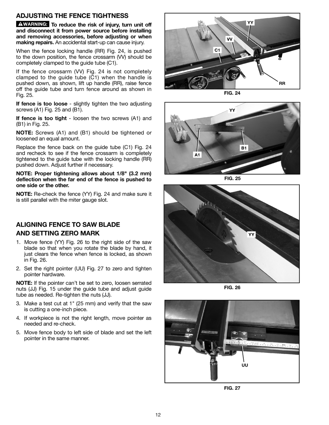
When the fence locking handle (RR) Fig. 24, is pushed to the down position, the fence crossarm (VV) should be completely clamped to the guide tube (C1).
If the fence crossarm (VV) Fig. 24 is not completely clamped to the guide tube (C1) when the handle is pushed down, as shown, lift up handle (RR), raise fence off the guide tube and turn fence around as shown in Fig. 25.
If fence is too loose - slightly tighten the two adjusting screws (A1) Fig. 25 and (B1).
If fence is too tight - loosen the two screws (A1) and (B1) in Fig. 25.
NOTE: Screws (A1) and (B1) should be tightened or loosened an equal amount.
Replace the fence back on the guide tube (C1) Fig. 24 and recheck to see if the fence crossarm is completely tightened to the guide tube with the locking handle (RR) pushed down. Adjust further if necessary.
NOTE: Proper tightening allows about 1/8" (3.2 mm) deflection when the far end of the fence is pushed to one side or the other.
NOTE:
ALIGNING FENCE TO SAW BLADE AND SETTING ZERO MARK
1.Move fence (YY) Fig. 26 to the right side of the saw blade so that when you rotate the blade by hand, it just clears the fence when fence is locked, as shown in Fig. 26.
2.Set the right pointer (UU) Fig. 27 to zero and tighten pointer hardware.
NOTE: If the pointer can’t be set to zero, loosen serrated nuts (JJ) Fig. 15 under the guide tube and adjust guide tube as needed.
3.Make a test cut at 1" (25 mm) and verify that the saw is cutting a
4.If workpiece is not the right length, move pointer as needed and
5.Move fence body to left side of blade and set the left pointer in the same manner.
YY
VV
C1
RR
Fig. 24
YY
B1
A1
Fig. 25
YY
Fig. 26
UU
Fig. 27
12