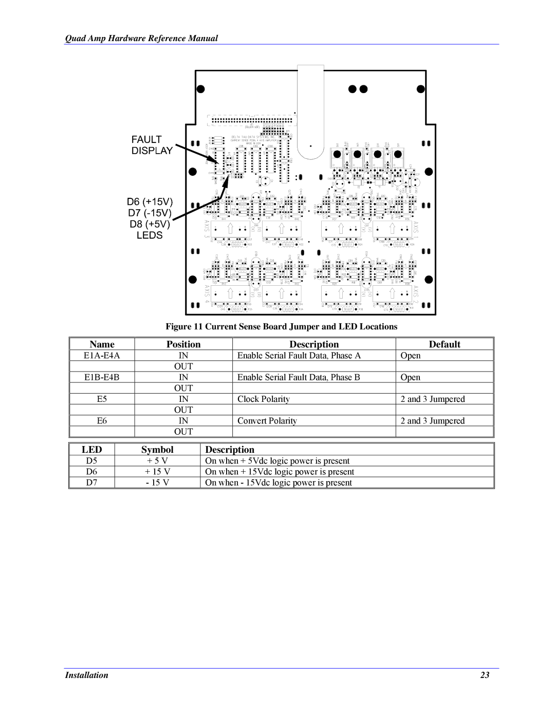
3Ax-602646-xUxx specifications
Delta Tau 3Ax-602646-xUxx is a cutting-edge motion controller designed for precision applications in automation and robotics. This model exemplifies advanced technology and innovative design, catering to industries ranging from manufacturing to aerospace. One of the key features of the Delta Tau 3Ax-602646-xUxx is its capability to control three axes simultaneously, allowing for synchronous motion that is critical in high-speed applications.At the core of its functionality is its robust processing unit, which supports high-speed data handling and complex algorithms for motion control. This allows the user to achieve precise positioning and trajectory control, essential for tasks such as CNC machining or robotic arms. The controller operates with real-time feedback, ensuring that any deviations in motion are corrected instantly, thereby enhancing reliability and performance.
The Delta Tau 3Ax-602646-xUxx incorporates a user-friendly interface, which simplifies the programming of motion sequences. Its compatibility with various programming languages and protocols such as C, C++, and PLC languages makes it an adaptable choice for engineers. Furthermore, it supports a range of standard communication protocols, enabling seamless integration with existing systems and devices.
One of the standout technological features of this controller is its adaptive control strategy. This allows the system to learn from past operations and adjust its parameters to optimize performance, making it suitable for applications that require high levels of precision and repeatability. The Delta Tau 3Ax-602646-xUxx also utilizes advanced algorithms for PID control, ensuring smooth acceleration and deceleration, which is vital for maintaining component integrity in delicate manufacturing processes.
Another significant characteristic is its ability to interface with a variety of sensors and feedback devices, providing enhanced environmental awareness. This feature significantly boosts the controller's versatility as it can adapt to different machinery and operational challenges easily. Additionally, the system is designed to be scalable, accommodating future upgrades or expansions, thus offering long-term investment value for businesses.
In summary, the Delta Tau 3Ax-602646-xUxx is a powerful motion controller that combines precision, versatility, and advanced technology. Its simultaneous axis control, robust processing capabilities, user-friendly interface, and adaptive features make it an essential tool for modern automation and robotics applications, ensuring high levels of efficiency and productivity.

