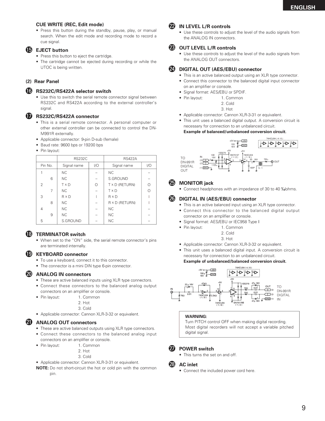
DN-M991R specifications
The Denon DN-M991R is a professional-grade dual CD player that has become a favorite among DJs and audio professionals for its blend of reliability, advanced features, and ease of use. Designed for both live performance and studio applications, the DN-M991R offers a range of technologies and characteristics that cater to the needs of modern audio environments.First and foremost, the DN-M991R features dual CD playback, allowing users to seamlessly mix tracks from two separate CD sources. This capability is essential for DJs who need to maintain energy on the dance floor while effortlessly transitioning between songs. The player also supports a wide range of audio formats, including standard audio CDs and CD-R/RW discs, providing flexibility for users who may have various media formats.
One of the standout technologies in the DN-M991R is its precision-engineered jog wheel. The highly responsive jog wheel offers precise control over track selection and scrubbing, making it easy to perform live remixes and adjustments on the fly. Additionally, the DN-M991R is equipped with a fluent pitch control range, featuring both fine and coarse adjustments, allowing artists to manipulate tempo with accuracy.
The device also boasts a 20-second anti-shock buffer, which effectively minimizes interruptions during performances. This technology is critical for DJs working in high-energy environments where sudden movements or vibrations can lead to playback issues.
Connectivity is another key aspect of the DN-M991R. It comes with balanced XLR outputs, unbalanced RCA outputs, and digital outputs, making it compatible with a broad range of sound systems and setups. Furthermore, the player supports MIDI, enabling integration with DJ software for enhanced performance possibilities.
User-friendly navigation is facilitated via a large LCD display, providing clear track information and intuitive menus. The DN-M991R also includes a range of effects and features such as seamless looping, cue points, and pitch bend functionality, enhancing the creative palette for DJs.
In summary, the Denon DN-M991R is a robust dual CD player that integrates advanced technology, crucial features, and versatility into one compact unit. Its reliable performance, comprehensive connectivity options, and user-friendly interface make it an essential tool for both aspiring and professional DJs in diverse audio settings. Whether used in a club, a mobile setup, or a studio, the DN-M991R continues to be recognized for its superior quality and performance.

