OWNER’S MANUAL
OPERATING STOVE WITH B-VENT BURNER SYSTEM
Continued
OPERATING
OPTIONAL GWMT1
WALL MOUNTED
THERMOSTAT
![]() WARNING: Do not connect the thermostat to a power source. Electrical shock and/or a fire haz- ard will occur.
WARNING: Do not connect the thermostat to a power source. Electrical shock and/or a fire haz- ard will occur.
Light the fireplace as instructed in Light- ing Instructions on page 19. Set wall ther- mostat to desired temperature.
This thermostat has been electronically calibrated at the factory and requires no adjustment or leveling.
OPERATING
OPTIONAL BLOWER
ACCESSORY
Blower controls are located on the left side of the rear cover of stove (from front of stove).
The DA3610TA
If you are using DA3610TA blower with optional thermostat (wall mount or re- mote control), your burner system and blower will not turn on and off at the same time. The burner system may run for several minutes before the blower turns on. After the heater modulates to the pilot position, the blower will con- tinue to run. The blower will shut off after the burner system firebox temperature decreases.
The blower helps distribute heated air from the burner system. Periodically check the top grates of the stove and remove any dust, dirt, or other obstruc- tions that will hinder the flow of air.
Upon installation, the thermostat must be allowed to stabilize at room tempera- ture for a minimum of 30 minutes for proper operation.
To turn the burner system off, adjust thermostat to the lowest setting and turn the gas control knob back to PILOT. The pilot will remain lit.
IMPORTANT: To turn the pilot off, turn the control knob on the heater to the OFF position.
INSPECTING
BURNERS
Check pilot flame pattern and burner flame patterns often.
PILOT ASSEMBLY
The pilot assembly is factory preset for the proper flame height. Alterations may have occurred during shipping and handling. Call a qualified service person to readjust the pilot if necessary.
The height of the thermopile must be 3/8" to 1/2" above the pilot flame as shown in Figure 53. The flame from the pilot burner must extend beyond the thermopile.
If your pilot assembly does not meet these requirements:
•turn burner system off (see To Turn Off Gas to Appliance, page 19)
•seeTroubleshooting, pages 23 through 25
Thermopile
3/8" to 1/2"
Pilot Burner
Piezo Ignitor
Figure 53 - Pilot Assembly
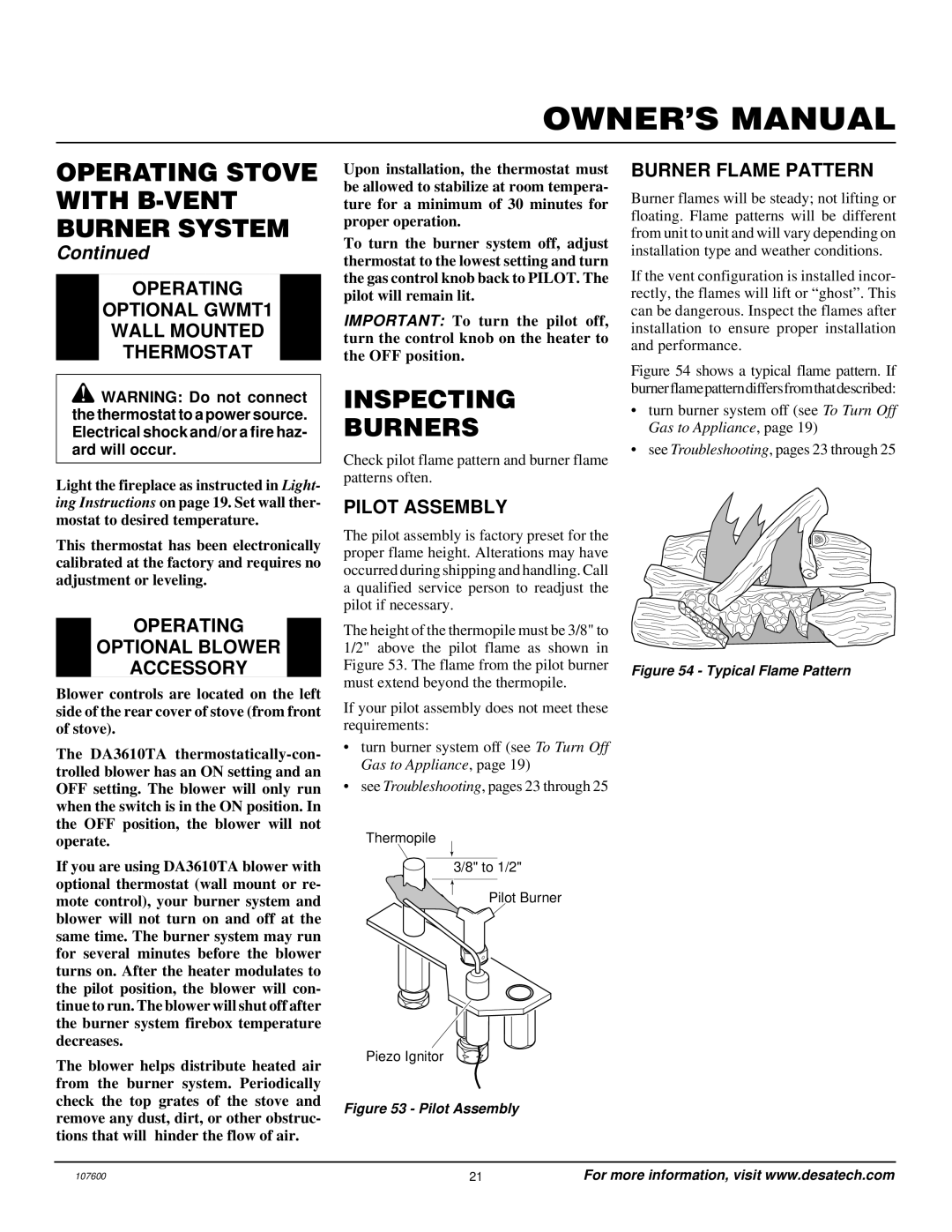
BURNER FLAME PATTERN
Burner flames will be steady; not lifting or floating. Flame patterns will be different from unit to unit and will vary depending on installation type and weather conditions.
If the vent configuration is installed incor- rectly, the flames will lift or “ghost”. This can be dangerous. Inspect the flames after installation to ensure proper installation and performance.
Figure 54 shows a typical flame pattern. If burnerflamepatterndiffersfromthatdescribed:
•turn burner system off (see To Turn Off Gas to Appliance, page 19)
•seeTroubleshooting, pages 23 through 25
Figure 54 - Typical Flame Pattern
107600 | 21 | For more information, visit www.desatech.com |