Cleaning and
Maintenance
Continued
4.Check the injector holder located at the end of the burner tube again. Remove any large particles of dust, dirt, lint or pet hair with a soft cloth or vacuum cleaner nozzle.
5.Blow air into the primary air holes on the injector holder.
6.In case any large clumps of dust have now been pushed into the burner repeat steps 3 and 4.
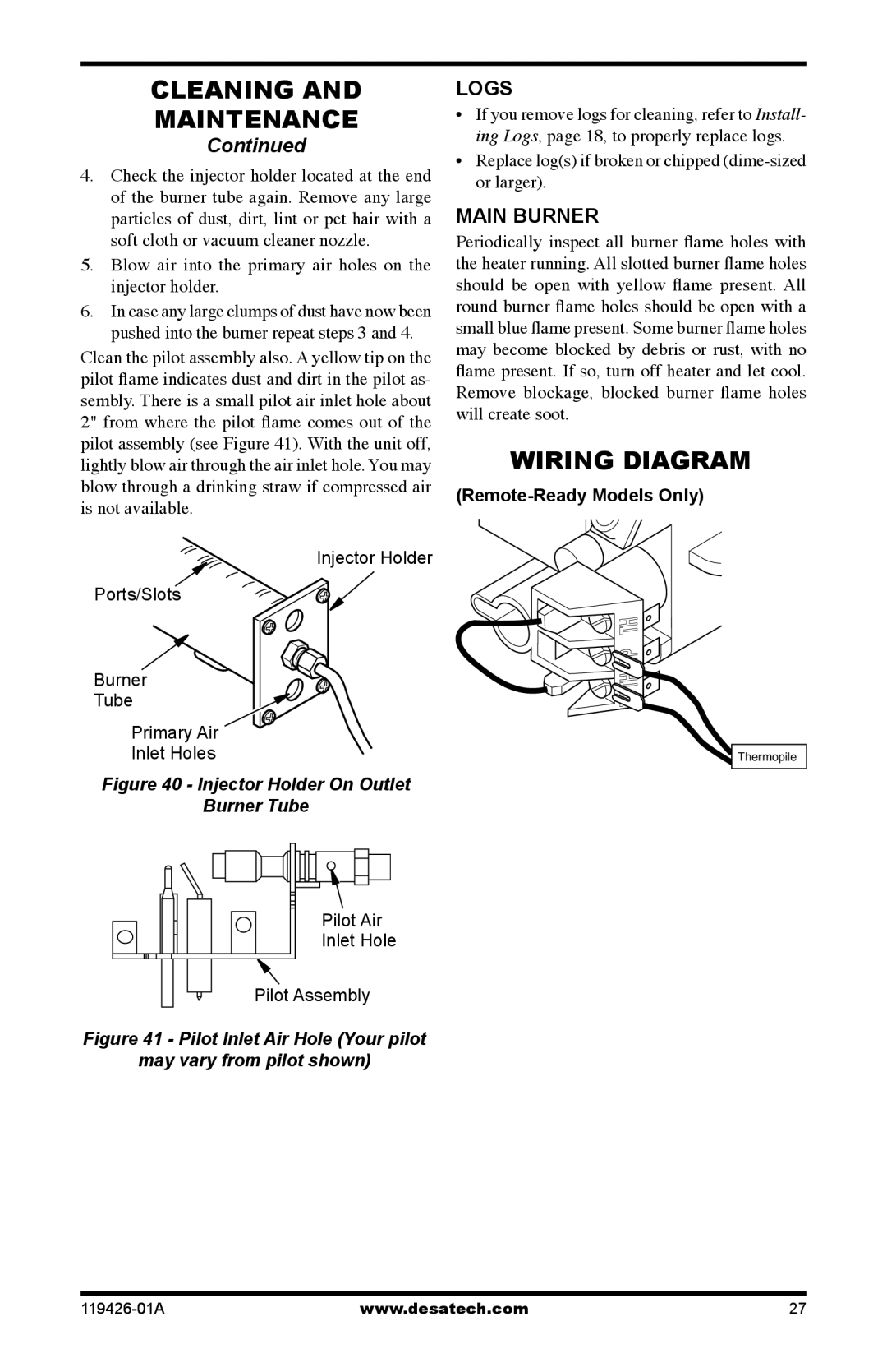
Clean the pilot assembly also. A yellow tip on the pilot flame indicates dust and dirt in the pilot as- sembly. There is a small pilot air inlet hole about 2" from where the pilot flame comes out of the pilot assembly (see Figure 41). With the unit off, lightly blow air through the air inlet hole. You may blow through a drinking straw if compressed air is not available.
Injector Holder
Ports/Slots
Burner
Tube
Primary Air
Inlet Holes
Figure 40 - Injector Holder On Outlet
Burner Tube
Pilot Air
Inlet Hole
Pilot Assembly
Figure 41 - Pilot Inlet Air Hole (Your pilot
may vary from pilot shown)
LOGS
•If you remove logs for cleaning, refer to Install- ing Logs, page 18, to properly replace logs.
•Replace log(s) if broken or chipped
main burner
Periodically inspect all burner flame holes with the heater running. All slotted burner flame holes should be open with yellow flame present. All round burner flame holes should be open with a small blue flame present. Some burner flame holes may become blocked by debris or rust, with no flame present. If so, turn off heater and let cool. Remove blockage, blocked burner flame holes will create soot.
Wiring Diagram
(Remote-Ready Models Only)
Thermopile
www.desatech.com | 27 |