8
VENTING INSTALLATION INSTRUCTIONS Installation Planning
VENTING INSTALLATION INSTRUCTIONS
Continued
2.Direct vent pipe sections and components are designed with special
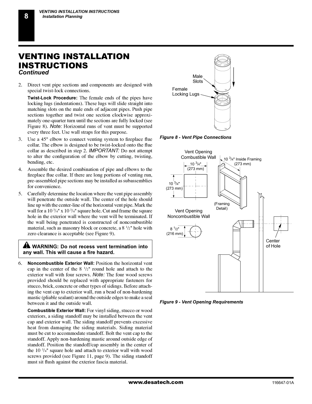
Male
Slots ![]()
Female
Locking Lugs
3. | Use a 45° elbow to connect venting system to fireplace flue | Figure 8 - Vent Pipe Connections | ||||||
|
| |||||||
| collar. The elbow is designed to be |
|
| |||||
| collar as described in step 2. IMPORTANT: Do not attempt | Vent Opening |
| |||||
| to alter the configuration of the elbow by cutting, twisting, | Combustible Wall | 10 3/4" Inside Framing | |||||
| bending, etc. |
|
|
|
|
| ||
4. |
|
|
|
|
| 10 3/4" | (273 mm) | |
Assemble the desired combination of pipe and elbows to the | (273 mm) |
| ||||||
| fireplace flue collar. If there are long portions of venting run, |
|
| |||||
| 10 3/4" |
| ||||||
| for convenience. |
|
|
|
|
|
| |
|
|
|
|
|
| (273 mm) |
| |
5. | Carefully determine the location where the vent pipe assembly |
| ||||||
|
| |||||||
| will penetrate the outside wall. The center of the hole should | (Framing | ||||||
| line up with the | |||||||
|
| Detail) | ||||||
| 3 | 3 |
|
|
|
| Vent Opening | |
| wall for a 10 /4" x 10 | /4" square hole. Cut and frame the square |
| |||||
| hole in the exterior wall where the vent will be terminated. If | Noncombustible Wall |
| |||||
| the wall being penetrated is constructed of noncombustible |
|
| |||||
| material, such as masonry block or concrete, a 8 | 1 | /2" hole with | 8 1/2" |
| |||
|
|
| ||||||
| zero clearance is acceptable (see Figure 9). |
|
| (216 mm) |
| |||
|
|
|
|
|
|
|
| Center |
| WARNING: Do not recess vent termination into |
| of Hole | |||||
| any wall. This will cause a fire hazard. |
|
|
|
| |||
6. | Noncombustible Exterior Wall: Position the horizontal vent |
|
| |||||
| cap in the center of the 8 | 1 | /2" round hole and | attach to the |
|
| ||
|
|
|
| |||||
| exterior wall with four screws. Note: The four wood screws |
|
| |||||
| provided should be replaced with appropriate fasteners for |
|
| |||||
| stucco, brick, concrete or other types of sidings. Before attach- |
|
| |||||
| ing the vent cap to exterior wall, run a bead of |
|
| |||||
| mastic (pliable sealant) around the outside edges to make a seal | Figure 9 - Vent Opening Requirements | ||||||
| between it and the outside wall. |
|
| |||||
Combustible Exterior Wall: For vinyl siding, stucco or wood | ||
exteriors, a siding standoff may be installed between the vent | ||
cap and exterior wall. The siding standoff prevents excessive | ||
heat from damaging the siding materials. Siding material | ||
must be cut to accommodate standoff. Bolt the vent cap to the | ||
standoff. Apply | ||
standoff. Position the standoff/cap assembly in the center of | ||
the 10 | 3 | /4" square hole and attach to exterior wall with wood |
|
| |
screws provided (see Figure 11, page 9). The siding standoff | ||
must sit flush against the exterior fascia material. | ||
www.desatech.com |