Heavy Duty Large Angle Grinders
Definitions Safety Guidelines
General Power Tool Safety Warnings
Work Area Safety
Electrical Safety
Stay alert
Use Common
Do not
For your
Safety iNSTRUCTiONS for
Service
ALL Operations
Abrasivej Cuing-OffOperations
Regularly clean the power tools air vents. The motors
Position the cord clear of the spinning accessory. /f you
Kickback and Related Warnings
Additional Safety Warnings Specific for
Safety Warnings Specific for Polishing Operations
Safety Warnings Specific for Sanding
Contactwithwheel,andsparksthatcouldigniteclothing
Additional Safety Rules for Grinders
Safety Warnings Specific for Wire
Brushing Operations
Save These iNSTRUCTiONS for
Future USE
Dust Ejection System
Familiarization
Toughcord TM System
Switch Protection TM
AttacMng
Side Handle Fig
DWE4597, DWE4597N, DWE4599N
FIG3. \
Wheel Mountin9 Accessories Attachments
Attach M Ents
Sanding Flap Discs
Mounting Guard
Mounting and Removing Guard
Type28hubbedwheel
Grinding Wheels Sanding Discs
Flaring Cup Stones
Wire Wheels
Wheels
Switch Fig
Operation
Reduce
When
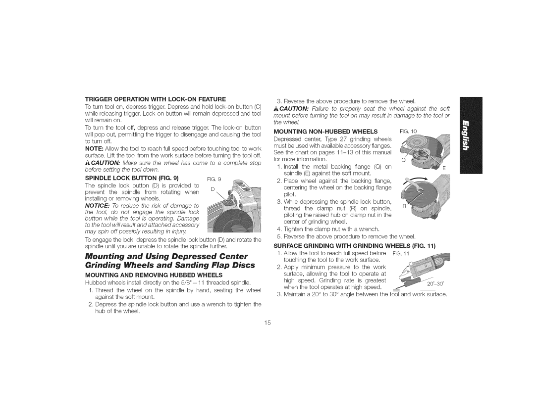
Trigger Operation with LOCK-ONFEATURE
Spindle Lock Button FIG
Mounting and Removing Hubbed Wheels
Mounting NON-HUBBED Wheels
Thewheeltostoprotatingbeforelayingthetooldown
Mounting Sanding Backing Pads FIG
Precautions To Take When Sanding Paint
Using Sanding Backing Pads FIG
Environ M Ental Safety
Sandingdiscwhiledepressingthespindlelockbutton
Mounting and Using Wire Brushes and Wire Wheels
Cleaning and Disposal
Mounting Wire CUP Brushes and Wire Wheels
Dustoutsidetheworkarea
Mounting and Using Cutting Type 1 Wheels
Mounting and Using Flaring Cup
Using a Flaring CUP Wheel FIG
Mounting Flaring CUP Wheel Guard FIG
Using Cutting Wheels
Mounting Cutting Wheels FIG
Maintenance
Thewheeltobendandmaycausewheelbreakage
Repairs
Register Online
Year Free Service
Three Year Limited Warranty
DAY Money Back Guarantee
Dfinitions Iignes directrices en rnatire de scurit
Aver*issernents de scurit gnraux
ET Toutes LES Directives Pour UN Usage Ulterieur
Pour les outils lectriques
SECURITi Personnelle
Nepas exposerlosoutils61ectriques b la pluie ou b
Utilisation ET Entretien Dunoutil ¢LECTRIOUE
Toutes L£S Operations
BNepas utiliserun outil61ectrique dent Iinterrupteur
#PARATION
Page
NNepasfairefonctionnerIoutil61ectrique b proximit6 de
Rebonds eft avertissernents all, rents
Avertissements de scurit spcifiques
Aux operations de rneulage et de coupe Par abrasion
Avertissernents de scurit
Supplrnentaires spcifiques aux
Rgles additionnelles de scurit propres
Aux rneuleuses
Non recommande
Conserver CES Consignes Pour
ULT E-RIEURE
Route
Pendant
Description j 9
POIGN#E Arriere ANTI-VIBRATIONS FIG
Systeme DI#VACUATION DES Poussieres
Carter Automatique
Installation De la poigne Latrale
Laterale H peut tre installee sur Iun ou
Embrayage
=CLUTCH Mc DWE4597, DWE4597N, DWE4599N
Positionnement de la poigne artiste
Installation de rneules et daccessoires
SEU LEM ENT
¢¢I=SSOI R I=S
Disques de pon age , feuillets
Dewalt
D284937po D284939po Type27hubbedwheel
D284938po
Meuleavecmoyeun28
Meules
Meules boisseaux
Brosses mdtalliques
Meules abrasives
Assemblage du capot protecteur
Assemblage ET Retrait DU Capot Protecteur
Interrupteur Fig
Fonctionnement
Utilisation DE Linterrupteur a Gachette
Installation DES Meules Sans Moyeu
Installation ET Reftrait DES Meules Avec Moyeu
Meulage DE Surface Avec DES Meules FIG
Meulagede Chant Avec DES Meules FIG
LetamponS
Toutenenfonantleboutondeverrouillage
La brochetouten tournantle disque
Abrasifjusquce quele disqueet
Respect DE Lenvironnement
SECURITiPERSONNELLE
Nettoyage ET Mise AU Rebut
Utilisation DE Brosses Forme Coupelle ET DE
Brosses Mtalliques a Touret FIG
INSTALLATiON DES Meules
Montage et utilisation de meules
Boisseaux Coniques FIG
Montage DU Capot Protecteur FERM¢ DE Type
Montage DE Disques DE Coupe FIG
Pourretirerlecapotprotecteur,degager
Utilisation DE Disques DE Coupe
Neoyage
Accessoires
Rparations
Remplacement Gratuit DES Etiquettes
Garantie lirnite de trois ans
Contrat Dentretien Gratuit DUN AN
Garantie DE Remboursement DE 90 Jours
Definiciones Normas de seguridad
Conserve Todas LAS Advebtencias
IADVERTENCIA! Lea todas las advertencias de seguridad
Seguridad EN EL Area DE Trabajo
Seguridad Personal
USO Y Mantenimiento DE LA Herramienta Electrica
Advertencias de seguridad comunes para
Instrucciones DE Segubidad Paba Todas LAS Opebaciones
Mantenimiento
Page
Bebote g advertencias relacionadas
Advertencias de seguridad especificas
Para operaciones de pulido
Para operaciones de cepillado con cepillo de alarnbre
Norrnas de seguridad adicionales para esrneriladoras
Largo total
GUARD£ Estas Instrucciones Para Futuras Consultas
RPM
Switch Protection TM Proteccion DE Interruptor Electronico
USO Debido
Mango Trasero Antivibraciones FIG
Sistema DE Extraccion DE Polvo
MONTAJ£ Y Ajustes
Fijaci6n
Mange
=CLUTCH TM
Rotaci6n de la caja de engranajes Fig
Como girar mango trasero Fig
Accesorios y dispositivos para el montaje de los discos
D28499 Solamente
Sanding Flap Discs
Dispositivos
Guardatipo27 D2849377 D2849399 Discodetipo27
Guardatipo28 D2849389
Discotipo28
Discos de lijar
Copa de Piedra
Ce illos de alambre
Discos de corse
Protector de rnontaje
Montaje Y Extraccion DEL Protector
ATENCI6N
Accesorio podria
Interrupter Fig
FUNCIONAMI£NTO
Encendido Permanente
Esmerilado DE Superficie CON Discos DE Esmerilar
Instalacidn DE Discos CON Centro Deprimido
Esmerilado DE Bordes CON Discos DE Esmerilar FIG
Acabado DE Superficies CON Discos DE Lijar FIG
Montaje DE LAS Almohadillas DE Respaldo Para Lijar FIG
Precauciones que debe tenet en cuenta
Al lijar pintura
USO DE Almohadillas DE Respaldo Para Lijar FIG
Seguridad Personal
Discos Alambre
BeberofumarNosedebendejarartculosparacomer,beber
Reducir
Alambre. Pueden
Permitaquelaherramientaalcancelavelocidadm6,ximaantesde
Aplicarlalasuperficiedetrabajo
Sobreunasuperficie
Instalaci6n y utilizaci6n de piedras
Antesdeusarelesmerilador
SeextiendaApretarfirmementelostornillosdelacamisadelaguarda
Montaje y uso de discos de corte
Tipo 1
Parael di6,metrodelcubodela cajade
MANT£NIMi£NTO
Limpieza
Montaje DE LOS Discos DE Corte FIG
Accesorios
Reparaciones
P61iza De Garantia
SAN LUlS POTOSI, SLP
Para Otras Localidades
Identificacion DEL Producto
Garantia lirnitada por tres aos
Garantia DE Reembolso DE SU Dinero POR go Dias
Reemplazo Gratuito DE LAS Etiquetas DE
DWE4557 ,..I,o.ml
Especificaciones
DWE4557 DWE4599
DW4559
DW4579
Optimal
Capable --CANNOT be Used