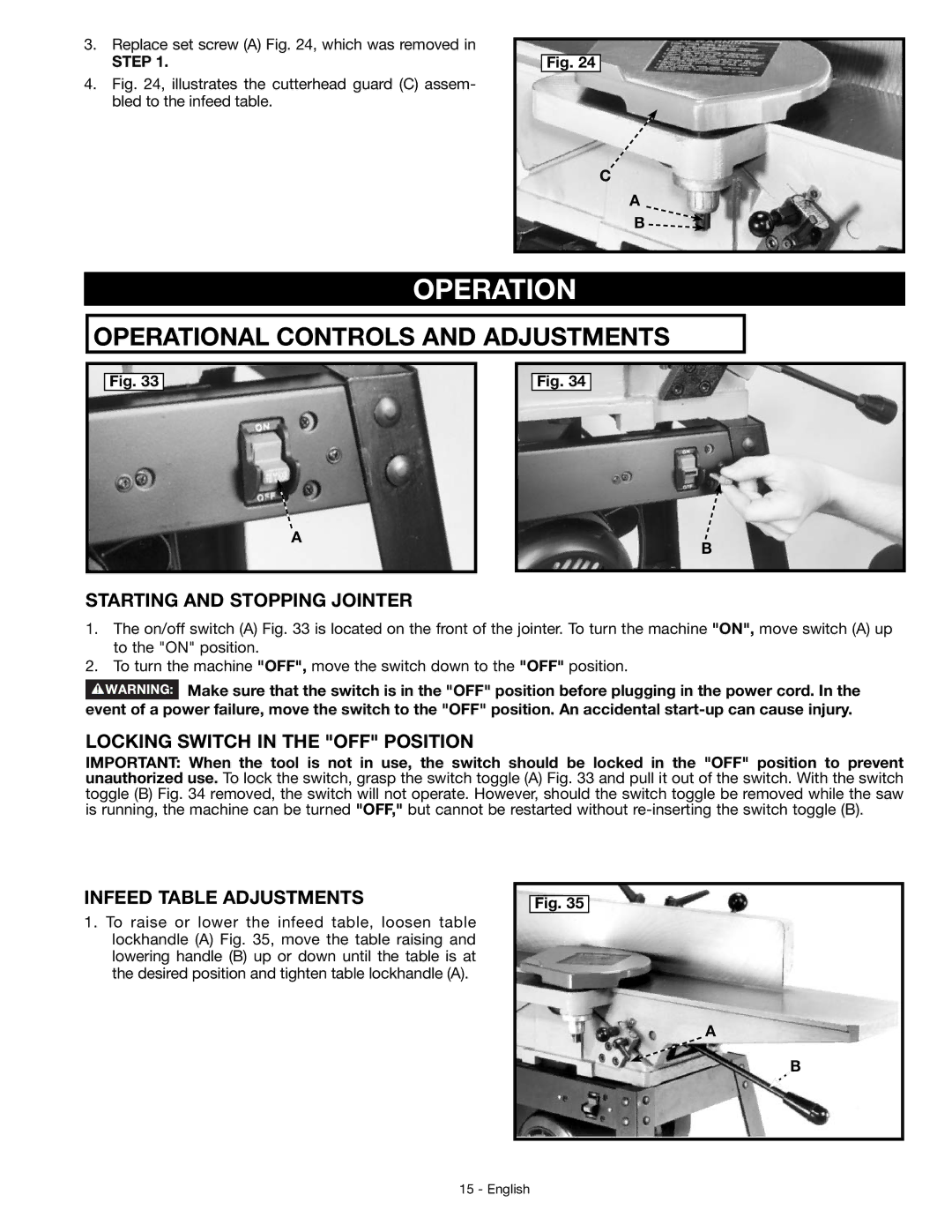
3.Replace set screw (A) Fig. 24, which was removed in
STEP 1.
4.Fig. 24, illustrates the cutterhead guard (C) assem- bled to the infeed table.
Fig. 24
C
A
B ![]()
OPERATION
OPERATIONAL CONTROLS AND ADJUSTMENTS
Fig. 33
Fig. 34
A
B
STARTING AND STOPPING JOINTER
1.The on/off switch (A) Fig. 33 is located on the front of the jointer. To turn the machine "ON", move switch (A) up to the "ON" position.
2.To turn the machine "OFF", move the switch down to the "OFF" position.
![]() Make sure that the switch is in the "OFF" position before plugging in the power cord. In the event of a power failure, move the switch to the "OFF" position. An accidental
Make sure that the switch is in the "OFF" position before plugging in the power cord. In the event of a power failure, move the switch to the "OFF" position. An accidental
LOCKING SWITCH IN THE "OFF" POSITION
IMPORTANT: When the tool is not in use, the switch should be locked in the "OFF" position to prevent unauthorized use. To lock the switch, grasp the switch toggle (A) Fig. 33 and pull it out of the switch. With the switch toggle (B) Fig. 34 removed, the switch will not operate. However, should the switch toggle be removed while the saw is running, the machine can be turned "OFF," but cannot be restarted without
INFEED TABLE ADJUSTMENTS
1.To raise or lower the infeed table, loosen table lockhandle (A) Fig. 35, move the table raising and lowering handle (B) up or down until the table is at the desired position and tighten table lockhandle (A).
Fig. 35
A
B
