INSTALLATION
Electrical connection | E |
The electrical connection depends on which water pump is installed; there are two variants:
1.
2.
Irrespective of which of the two pump systems is in use, the following applies:
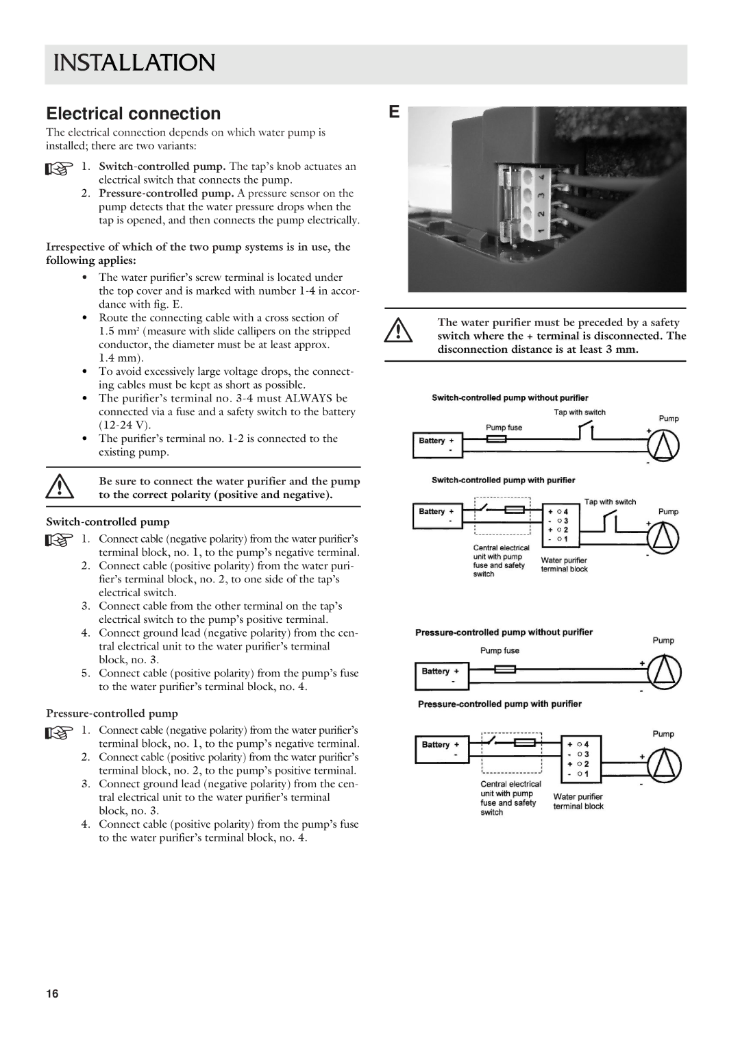
•The water purifier’s screw terminal is located under the top cover and is marked with number
•Route the connecting cable with a cross section of
1.5 mm2 (measure with slide callipers on the stripped conductor, the diameter must be at least approx.
1.4 mm).
•To avoid excessively large voltage drops, the connect- ing cables must be kept as short as possible.
•The purifier’s terminal no.
•The purifier’s terminal no.
Be sure to connect the water purifier and the pump to the correct polarity (positive and negative).
1. Connect cable (negative polarity) from the water purifier’s terminal block, no. 1, to the pump’s negative terminal.
2.Connect cable (positive polarity) from the water puri- fier’s terminal block, no. 2, to one side of the tap’s electrical switch.
3.Connect cable from the other terminal on the tap’s electrical switch to the pump’s positive terminal.
4.Connect ground lead (negative polarity) from the cen- tral electrical unit to the water purifier’s terminal block, no. 3.
5.Connect cable (positive polarity) from the pump’s fuse to the water purifier’s terminal block, no. 4.
Pressure-controlled pump
1. Connect cable (negative polarity) from the water purifier’s terminal block, no. 1, to the pump’s negative terminal.
2.Connect cable (positive polarity) from the water purifier’s terminal block, no. 2, to the pump’s positive terminal.
3.Connect ground lead (negative polarity) from the cen- tral electrical unit to the water purifier’s terminal block, no. 3.
4.Connect cable (positive polarity) from the pump’s fuse to the water purifier’s terminal block, no. 4.
The water purifier must be preceded by a safety switch where the + terminal is disconnected. The disconnection distance is at least 3 mm.
16
