DYNAFLEX ELASTOMERIC FLEXIBLE COUPLINGS | Page 102 of 124 | |
|
|
|
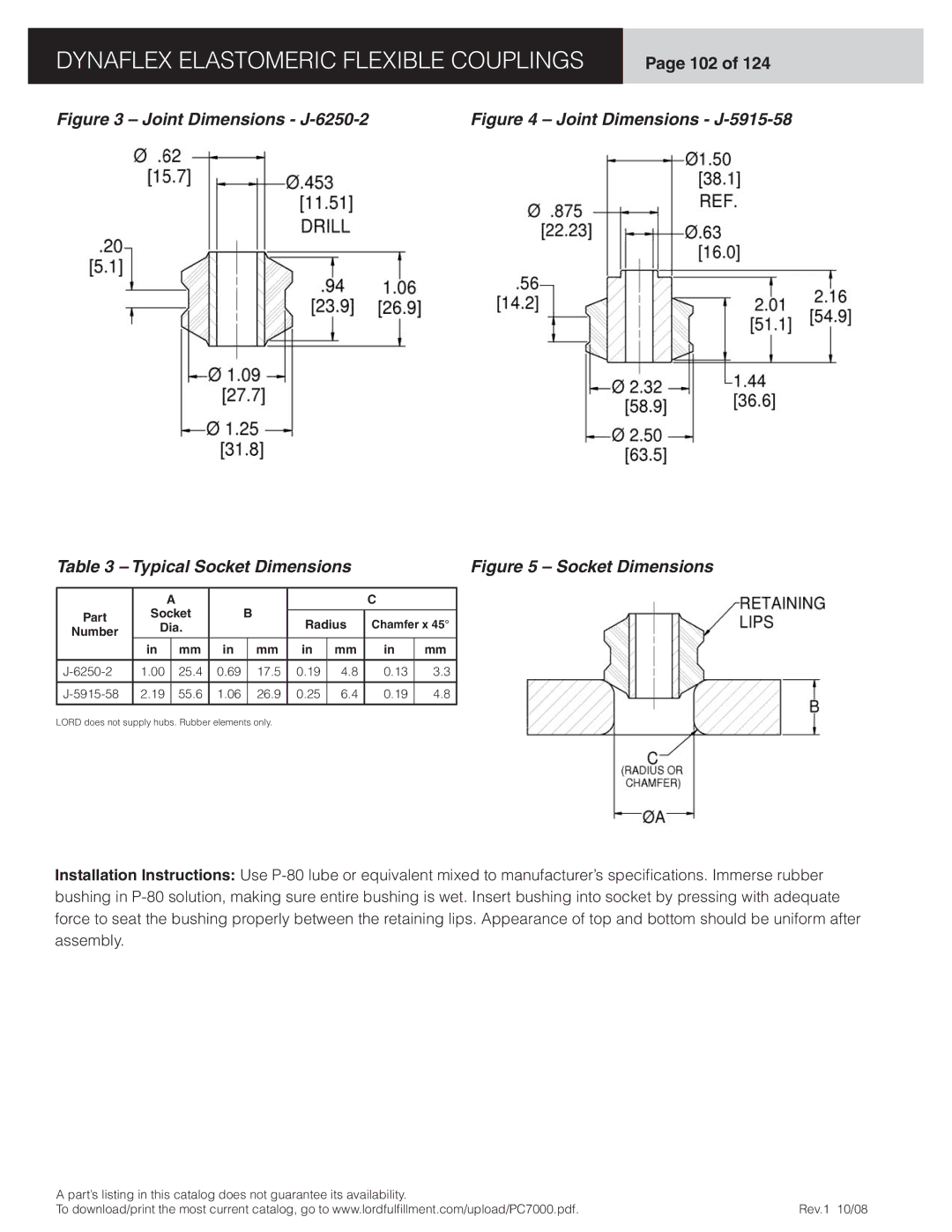
Figure 3 – Joint Dimensions - | Figure 4 – Joint Dimensions - | |
Table 3 – Typical Socket Dimensions |
|
| Figure 5 – Socket Dimensions | ||||||||
|
|
|
|
|
|
|
|
|
|
|
|
|
| A |
|
|
|
|
| C |
|
| |
Part | Socket |
| B |
|
|
|
|
| |||
| Radius | Chamfer x 45° |
| ||||||||
Dia. |
|
|
|
| |||||||
Number |
|
|
|
| |||||||
| in |
| mm | in |
| mm | in | mm | in | mm |
|
|
|
|
|
|
|
|
|
|
|
|
|
1.00 |
| 25.4 | 0.69 |
| 17.5 | 0.19 | 4.8 | 0.13 | 3.3 |
| |
|
|
|
|
|
|
|
|
|
|
|
|
2.19 |
| 55.6 | 1.06 |
| 26.9 | 0.25 | 6.4 | 0.19 | 4.8 |
| |
|
|
|
|
|
|
|
|
|
|
|
|
LORD does not supply hubs. Rubber elements only.
Installation Instructions: Use
A part’s listing in this catalog does not guarantee its availability. |
|
To download/print the most current catalog, go to www.lordfulfi llment.com/upload/PC7000.pdf. | Rev.1 10/08 |
