DYNAFLEX ELASTOMERIC FLEXIBLE COUPLINGS Page 101 of 124
Dynaflex Bushing-Type Couplings
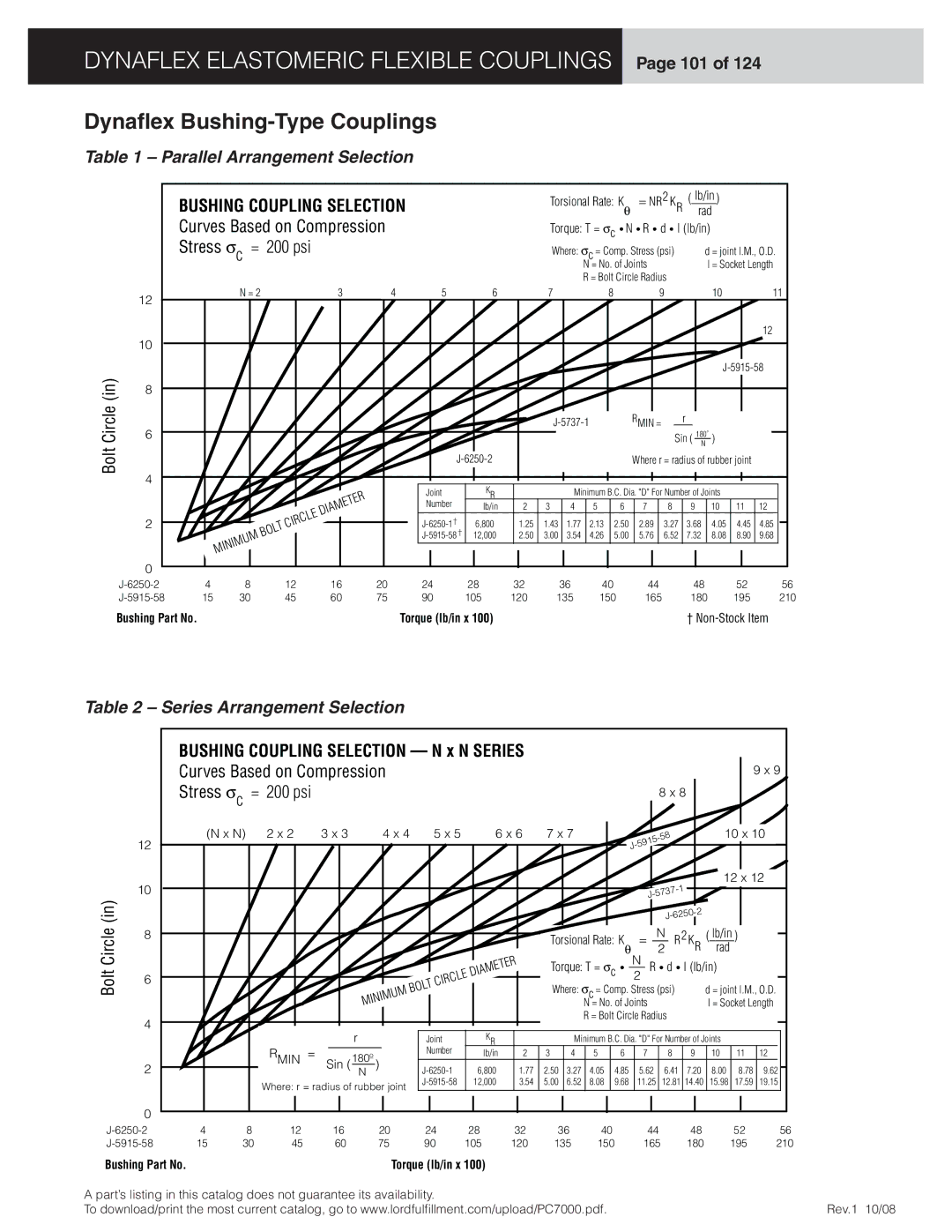
Table 1 – Parallel Arrangement Selection
|
| 2 |
| lb/in |
BUSHING COUPLING SELECTION | Torsional Rate: Kθ = NR | KR | (____) | |
| rad | |||
Curves Based on Compression | Torque: T = σc • N • R • d • l (lb/in) | |||
Stress σc = 200 psi | Where: σc = Comp. Stress (psi) | d = joint l.M., O.D. | ||
| N = No. of Joints |
|
| l = Socket Length |
R = Bolt Circle Radius
| 12 |
| N = 2 |
| 3 | 4 | 5 | 6 |
| 7 |
| 8 |
| 9 |
|
| 10 |
| 11 |
|
|
|
|
|
|
|
|
|
|
|
|
|
|
|
|
|
|
| |
|
|
|
|
|
|
|
|
|
|
|
|
|
|
|
|
|
|
| 12 |
| 10 |
|
|
|
|
|
|
|
|
|
|
|
|
|
|
|
|
|
|
(in) |
|
|
|
|
|
|
|
|
|
|
|
|
|
|
|
| |||
8 |
|
|
|
|
|
|
|
|
|
|
|
|
|
|
|
|
|
| |
|
|
|
|
|
|
|
|
|
|
|
|
|
|
|
|
|
|
| |
Circle | 6 |
|
|
|
|
|
|
|
|
|
| RMIN = |
| r |
|
|
| ||
|
|
|
|
|
|
|
|
|
|
|
|
| Sin ( 180˚N ) |
|
| ||||
Bolt |
|
|
|
|
|
|
|
|
|
|
|
| Where r = radius of rubber joint |
| |||||
4 |
|
|
|
|
|
|
|
|
|
|
|
|
|
|
|
|
|
| |
|
|
|
|
|
|
| KR |
|
|
|
|
|
|
|
|
|
|
| |
|
|
|
|
|
|
| Joint |
|
| Minimum B.C. Dia. "D" For Number of Joints |
|
| |||||||
|
|
|
|
| DIAMETER |
| Number | lb/in | 2 | 3 | 4 | 5 | 6 | 7 | 8 | 9 | 10 | 11 | 12 |
| 2 |
|
| CIRCLE |
| 6,800 | 1.25 | 1.43 | 1.77 | 2.13 | 2.50 | 2.89 | 3.27 | 3.68 | 4.05 | 4.45 | 4.85 | ||
|
| BOLT |
|
| |||||||||||||||
|
|
|
|
|
| 12,000 | 2.50 | 3.00 | 3.54 | 4.26 | 5.00 | 5.76 | 6.52 | 7.32 | 8.08 | 8.90 | 9.68 | ||
|
| MINIMUM |
|
|
|
|
|
|
|
|
|
|
|
|
|
|
|
| |
| 0 |
|
|
|
|
|
|
|
|
|
|
|
|
|
|
|
|
|
|
| 4 | 8 | 12 | 16 | 20 | 24 | 28 | 32 |
| 36 | 40 |
| 44 |
| 48 |
| 52 | 56 | |
| 15 | 30 | 45 | 60 | 75 | 90 | 105 | 120 | 135 | 150 | 165 |
| 180 |
| 195 | 210 | |||
| Bushing Part No. |
|
|
|
|
| Torque (lb/in x 100) |
|
|
|
|
|
|
| † | ||||
Table 2 – Series Arrangement Selection
Bolt Circle (in)
12
10
8
6
4
BUSHING COUPLING SELECTION — N x N SERIES Curves Based on Compression
Stress σc = 200 psi
(N x N) 2 x 2 | 3 x 3 | 4 x 4 | 5 x 5 | 6 x 6 |
| DIAMETER |
BOLT | CIRCLE |
|
MINIMUM
|
|
|
|
|
|
|
|
|
|
|
|
|
|
|
| 9 x 9 | ||
|
|
|
|
|
|
|
| 8 x 8 |
|
|
|
|
|
|
| |||
|
|
|
|
|
|
|
|
|
|
|
|
|
|
|
|
| ||
7 x 7 |
|
|
|
|
|
|
|
|
|
|
|
|
| 10 x 10 |
| |||
|
|
|
|
|
|
| ||||||||||||
|
|
|
|
| 5915 |
|
|
|
|
|
|
|
|
|
| |||
|
|
|
| J- |
|
|
|
|
|
|
|
|
|
|
|
| ||
|
|
|
|
|
|
|
|
|
|
|
|
|
|
|
|
|
| |
|
|
|
|
|
|
|
|
|
|
|
|
| 12 x 12 |
| ||||
|
|
|
|
|
|
|
|
|
|
|
|
|
|
|
|
| ||
|
|
|
|
|
|
|
|
|
|
|
|
|
|
|
|
| ||
|
|
|
|
|
|
|
|
|
|
|
|
|
|
| ||||
|
|
|
|
|
|
|
|
|
|
|
|
|
|
|
|
| ||
|
|
|
|
|
|
|
|
|
|
|
|
|
| |||||
Torsional Rate: K |
|
| = |
| N |
| R | 2 | K | ( lb/in ) |
| |||||||
|
|
|
| |||||||||||||||
θ | 2 |
|
| R rad | ||||||||||||||
|
|
| N |
|
|
|
| |||||||||||
Torque: T = σc • |
| R • d • l (lb/in) | ||||||||||||||||
| 2 |
| ||||||||||||||||
|
|
|
|
|
|
|
|
|
|
|
|
| ||||||
Where: σc = Comp. Stress (psi) |
|
| d = joint l.M., O.D. | |||||||||||||||
| N = No. of Joints |
|
|
| l = Socket Length | |||||||||||||
R = Bolt Circle Radius
2
|
|
| r |
|
| Joint | KR |
|
| Minimum B.C. Dia. "D" For Number of Joints |
|
|
|
| ||||||
RMIN | = |
| 180º |
|
| Number | lb/in | 2 | 3 | 4 | 5 | 6 | 7 | 8 | 9 | 10 | 11 | 12 |
|
|
|
|
|
|
|
| |||||||||||||||
|
|
|
|
|
|
|
|
|
|
|
|
|
|
|
|
| ||||
| Sin ( | N | ) |
| 6,800 | 1.77 | 2.50 | 3.27 | 4.05 | 4.85 | 5.62 | 6.41 | 7.20 | 8.00 | 8.78 | 9.62 |
| |||
|
|
| ||||||||||||||||||
Where: r = radius of rubber joint | 12,000 | 3.54 | 5.00 | 6.52 | 8.08 | 9.68 | 11.25 | 12.81 | 14.40 | 15.98 | 17.59 | 19.15 |
| |||||||
|
|
|
|
|
|
|
|
|
|
|
|
|
|
| ||||||
0
4 | 8 | 12 | 16 | 20 | 24 | 28 | 32 | 36 | 40 | 44 | 48 | 52 | 56 | |
15 | 30 | 45 | 60 | 75 | 90 | 105 | 120 | 135 | 150 | 165 | 180 | 195 | 210 | |
Bushing Part No. |
|
|
|
|
| Torque (lb/in x 100) |
|
|
|
|
|
|
| |
A part’s listing in this catalog does not guarantee its availability. |
|
|
|
|
|
|
|
| ||||||
To download/print the most current catalog, go to www.lordfulfi llment.com/upload/PC7000.pdf. |
|
|
| Rev.1 10/08 | ||||||||||