DYNAFLEX ELASTOMERIC FLEXIBLE COUPLINGS | Page 112 of 124 |
|
|
Selection Guide
This selection guide can be used to determine the size and series coupling to suit your general requirements. Final selection of the specifi c coupling to satisfy all of the application requirements generally necessitates
a system engineering analysis. These computerized analyses of torsional systems can be provided by LORD Corporation’s Engineering Department.
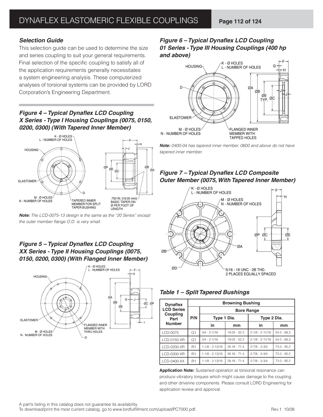
Figure 4 – Typical Dynaflex LCD Coupling
X Series - Type I Housing Couplings (0075, 0150, 0200, 0300) (With Tapered Inner Member)
Figure 6 – Typical Dynaflex LCD Coupling
01 Series - Type III Housing Couplings (400 hp and above)
Note:
tapered inner member.
Figure 7 – Typical Dynaflex LCD Composite
Outer Member (0075, With Tapered Inner Member)
Note: The
the outer member fl ange O.D. is very small.
Figure 5 – Typical Dynaflex LCD Coupling
XXSeries - Type II Housing Couplings (0075, 0150, 0200, 0300) (With Flanged Inner Member)
Table 1 – Split Tapered Bushings
Dynaflex |
|
| Browning Bushing |
| |||
|
|
|
|
|
| ||
LCD Series |
|
|
| Bore Range |
| ||
Coupling |
|
|
|
|
|
| |
P/N | Type 1 Dia. | Type 2 Dia. | |||||
Part | |||||||
Number |
| in |
| mm | in | mm | |
|
|
| |||||
|
|
|
|
|
|
| |
Q1 | 3/4 - |
| 19.05 - 52.3 | 54.0 - 68.3 | |||
|
|
|
|
|
|
| |
Q1 | 3/4 - |
| 19.05 - 52.3 | 54.0 - 68.3 | |||
|
|
|
|
|
|
| |
R1 |
| 28.16 - 71.4 | 73.0 - 95.2 | ||||
|
|
|
|
|
|
| |
R1 |
| 28.16 - 71.4 | 73.0 - 95.2 | ||||
|
|
|
|
|
|
| |
R1 |
| 28.16 - 71.4 | 73.0 - 95.2 | ||||
|
|
|
|
|
|
| |
Application Note: Sustained operation at torsional resonance can produce vibratory torques which might cause damage to the coupling and other driveline components. Please consult LORD Engineering for application review and approval.
A part’s listing in this catalog does not guarantee its availability. |
|
To download/print the most current catalog, go to www.lordfulfi llment.com/upload/PC7000.pdf. | Rev.1 10/08 |
