DYNAFLEX ELASTOMERIC FLEXIBLE COUPLINGS Page 117 of 124
Installation
For engine applications, the outer member is usually bolted directly to the fl ywheel; for other applications, to a suitable adaptor. The inner member normally attaches to the driven shaft. The smaller LCD couplings generally have a tapered bore, which accommodates a standard split tapered bushing which grips the drive shaft. (Refer to Table 1 - Split Tapered Bushings). This confi guration provides easy installation.
Figures 15 and 16 on the next page show typical installations involving universal joints.
Figure 8
Table 5 – Flywheels for Engine Mounted Torque Converters - SAE J927 Nov 88
Converter |
| B |
| C | Tapped Holes | |||
Flywheel |
|
|
|
|
|
|
|
|
in |
| mm | in |
| mm | No. | Size | |
No. |
|
| ||||||
|
|
|
|
|
|
|
|
|
20 | 9.50 |
| 241.30 | 8.750 |
| 222.25 | 12 | |
|
|
|
|
|
|
|
|
|
40 | 10.375 |
| 263.52 | 9.625 |
| 244.48 | 12 | |
|
|
|
|
|
|
|
|
|
60 | 13.875 |
| 352.42 | 13.125 |
| 333.38 | 12 | |
|
|
|
|
|
|
|
|
|
80 | 13.875 |
| 352.42 | 13.125 |
| 333.38 | 12 | |
|
|
|
|
|
|
|
|
|
100 | 13.875 |
| 352.42 | 13.125 |
| 333.38 | 12 | |
|
|
|
|
|
|
|
|
|
120 | 15.500 |
| 393.70 | 14.625 |
| 371.48 | 12 | |
|
|
|
|
|
|
|
|
|
140 | 18.375 |
| 466.72 | 17.250 |
| 438.15 | 12 | |
|
|
|
|
|
|
|
|
|
160 | 20.375 |
| 517.52 | 19.250 |
| 488.95 | 12 | |
|
|
|
|
|
|
|
|
|
180 | 22.500 |
| 571.52 | 21.375 |
| 542.92 | 12 | |
|
|
|
|
|
|
|
|
|
210 | 26.500 |
| 673.10 | 25.250 |
| 641.35 | 12 | |
|
|
|
|
|
|
|
|
|
240 | 28.875 |
| 733.42 | 27.250 |
| 642.15 | 12 | |
|
|
|
|
|
|
|
|
|
This arrangement must not be used. Suitable bearing supports are required to react
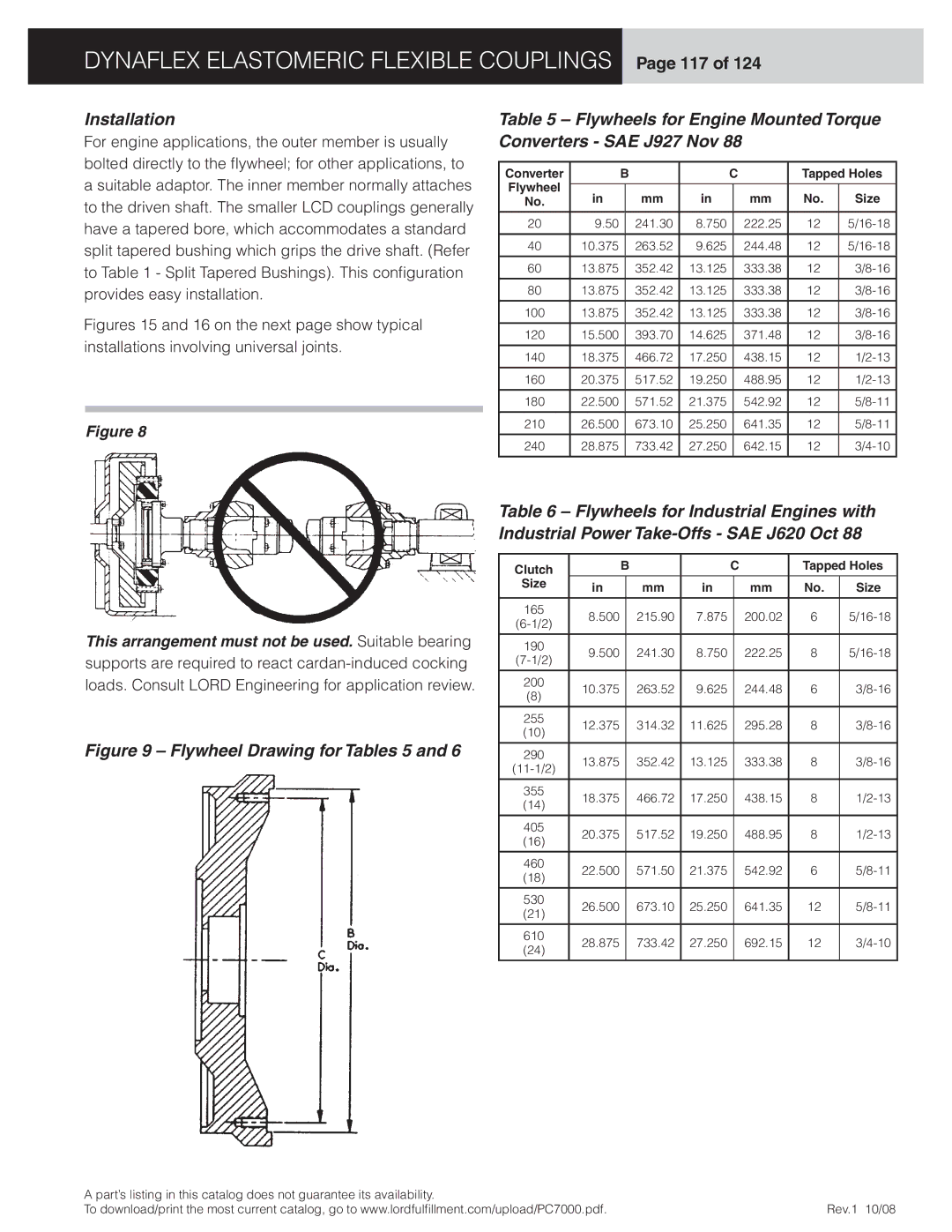
Figure 9 – Flywheel Drawing for Tables 5 and 6
Table 6 – Flywheels for Industrial Engines with Industrial Power Take-Offs - SAE J620 Oct 88
Clutch |
| B |
| C | Tapped Holes | |||
|
|
|
|
|
|
|
| |
Size | in |
| mm | in |
| mm | No. | Size |
|
|
| ||||||
|
|
|
|
|
|
|
|
|
165 | 8.500 |
| 215.90 | 7.875 |
| 200.02 | 6 | |
|
| |||||||
|
|
|
|
|
|
|
| |
|
|
|
|
|
|
|
|
|
190 | 9.500 |
| 241.30 | 8.750 |
| 222.25 | 8 | |
|
| |||||||
|
|
|
|
|
|
|
| |
|
|
|
|
|
|
|
|
|
200 | 10.375 |
| 263.52 | 9.625 |
| 244.48 | 6 | |
(8) |
|
| ||||||
|
|
|
|
|
|
|
| |
|
|
|
|
|
|
|
|
|
255 | 12.375 |
| 314.32 | 11.625 |
| 295.28 | 8 | |
(10) |
|
| ||||||
|
|
|
|
|
|
|
| |
|
|
|
|
|
|
|
|
|
290 | 13.875 |
| 352.42 | 13.125 |
| 333.38 | 8 | |
|
| |||||||
|
|
|
|
|
|
|
| |
|
|
|
|
|
|
|
|
|
355 | 18.375 |
| 466.72 | 17.250 |
| 438.15 | 8 | |
(14) |
|
| ||||||
|
|
|
|
|
|
|
| |
|
|
|
|
|
|
|
|
|
405 | 20.375 |
| 517.52 | 19.250 |
| 488.95 | 8 | |
(16) |
|
| ||||||
|
|
|
|
|
|
|
| |
|
|
|
|
|
|
|
|
|
460 | 22.500 |
| 571.50 | 21.375 |
| 542.92 | 6 | |
(18) |
|
| ||||||
|
|
|
|
|
|
|
| |
|
|
|
|
|
|
|
|
|
530 | 26.500 |
| 673.10 | 25.250 |
| 641.35 | 12 | |
(21) |
|
| ||||||
|
|
|
|
|
|
|
| |
|
|
|
|
|
|
|
|
|
610 | 28.875 |
| 733.42 | 27.250 |
| 692.15 | 12 | |
(24) |
|
| ||||||
|
|
|
|
|
|
|
| |
|
|
|
|
|
|
|
|
|
A part’s listing in this catalog does not guarantee its availability. |
|
To download/print the most current catalog, go to www.lordfulfi llment.com/upload/PC7000.pdf. | Rev.1 10/08 |