DYNAFLEX ELASTOMERIC FLEXIBLE COUPLINGS | Page 104 of 124 |
|
|
Typical Applications
Dynafl ex LCR Series Couplings are useful for a wide range of rotary drive applications, from lawn and garden tractors to large construction equipment, including
Typical End Product | Application |
|
|
Farm Tractor | |
|
|
Lawn & Garden Tractors | |
|
|
Dynamometer | Protects Driveline from Failure |
|
|
Snowmobile | Reliable Main Drive Coupling |
|
|
Vibratory Rollers | Absorbs High Torsional Shock Loads in |
| Eccentric Drive Units |
|
|
On- & | Isolates and Protects Vehicles Auxiliary |
| Driveline Systems |
|
|
Industrial Machinery | Provides Inexpensive Coupling for |
| Maximum Angular Misalignment and |
| Vibration Control |
|
|
Agriculture Equipment | Replaces Conventional Universal Joints |
| and Provides Torsional Flexibility |
|
|
Dynafl ex LCR Series Couplings were designed and developed by LORD and have been in service since the early 1960s. The basic concept was intended for specifi c applications requiring
The coupling design incorporates metal inserts bonded in an elastomeric ring, which loads the fl exing element in compression to transmit torque. Misalignment motion is accommodated by defl ecting the elastomer in shear, which allows extreme misalignment without high reaction forces.
They are ideally suited for
Absence of
is accomplished by insertion between simple parallel
flanges. This lightweight coupling element can be arranged in a single or double series confi guration to match specifi c torsional stiffness and misalignment requirements.
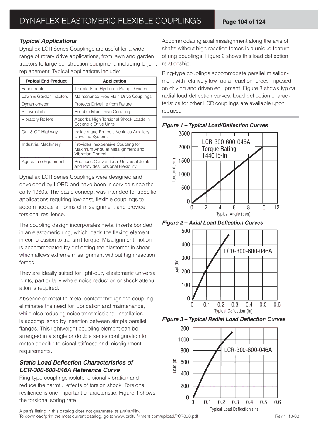
Static Load Deflection Characteristics of
Accommodating axial misalignment along the axis of shafts without high reaction forces is a unique feature of ring couplings. Figure 2 shows this load defl ection relationship.
Figure 1 – Typical Load/Deflection Curves
2500
| 2000 |
|
|
|
|
| ||||||||
|
| Torque Rating |
|
|
|
|
|
| ||||||
|
|
|
|
|
|
|
| |||||||
1500 |
| 1440 |
|
|
|
|
|
|
|
| ||||
|
|
|
|
|
|
|
|
| ||||||
|
|
|
|
|
|
|
|
|
|
|
|
| ||
|
|
|
|
|
|
|
|
|
|
|
|
| ||
(lb |
|
|
|
|
|
|
|
|
|
|
|
|
|
|
Torque | 1000 |
|
|
|
|
|
|
|
|
|
|
|
|
|
|
|
|
|
|
|
|
|
|
|
|
|
|
| |
| 500 |
|
|
|
|
|
|
|
|
|
|
|
|
|
|
|
|
|
|
|
|
|
|
|
|
|
|
| |
| 0 |
|
|
|
|
|
|
|
|
|
|
|
|
|
| 0 | 2 | 4 | 6 | 8 | 10 | 12 | |||||||
|
|
|
|
| Typical Angle (deg) |
|
|
|
| |||||
Figure 2 – Axial Load Deflection Curves |
|
| ||||||||||||
| 500 |
|
|
|
|
|
|
|
|
|
|
|
|
|
|
|
|
|
|
|
|
|
|
|
|
|
|
| |
| 400 |
|
|
|
|
|
|
|
|
|
|
|
|
|
|
|
|
|
|
|
|
|
|
|
|
|
|
| |
|
|
|
|
|
|
| ||||||||
| 300 |
|
|
|
|
|
| |||||||
(lb) |
|
|
|
|
|
|
|
|
|
|
|
|
| |
|
|
|
|
|
|
|
|
|
|
|
|
| ||
|
|
|
|
|
|
|
|
|
|
|
|
| ||
|
|
|
|
|
|
|
|
|
|
|
|
|
| |
Load | 200 |
|
|
|
|
|
|
|
|
|
|
|
|
|
|
|
|
|
|
|
|
|
|
|
|
|
|
| |
| 100 |
|
|
|
|
|
|
|
|
|
|
|
|
|
|
|
|
|
|
|
|
|
|
|
|
|
|
| |
| 0 |
|
|
|
|
|
|
|
|
|
|
|
|
|
| 0 | 0.1 | 0.2 | 0.3 | 0.4 | 0.5 | 0.6 | |||||||
Typical Deflection (in)
Figure 3 – Typical Radial Load Deflection Curves
| 1200 |
|
|
|
|
|
|
|
|
|
|
|
|
|
|
|
|
|
|
|
|
|
|
|
|
| |
| 1000 |
|
|
|
|
|
|
|
|
|
|
|
|
|
|
|
|
|
|
|
|
|
|
|
|
| |
(lb) | 800 |
|
|
|
|
|
| ||||||
|
|
|
|
| |||||||||
600 |
|
|
|
|
|
|
|
|
|
|
|
| |
|
|
|
|
|
|
|
|
|
|
|
| ||
|
|
|
|
|
|
|
|
|
|
|
| ||
Load |
|
|
|
|
|
|
|
|
|
|
|
| |
400 |
|
|
|
|
|
|
|
|
|
|
|
| |
|
|
|
|
|
|
|
|
|
|
|
|
| |
| 200 |
|
|
|
|
|
|
|
|
|
|
|
|
|
|
|
|
|
|
|
|
|
|
|
|
| |
| 0 |
|
|
|
|
|
|
|
|
|
|
|
|
|
| 0.1 | 0.2 | 0.3 | 0.4 | 0.5 | 0.6 | ||||||
| 0 | ||||||||||||
A part’s listing in this catalog does not guarantee its availability. | Typical Load Deflection (in) |
| |
To download/print the most current catalog, go to www.lordfulfi llment.com/upload/PC7000.pdf. | Rev.1 10/08 |