DYNAFLEX ELASTOMERIC FLEXIBLE COUPLINGS | Page 118 of 124 |
|
|
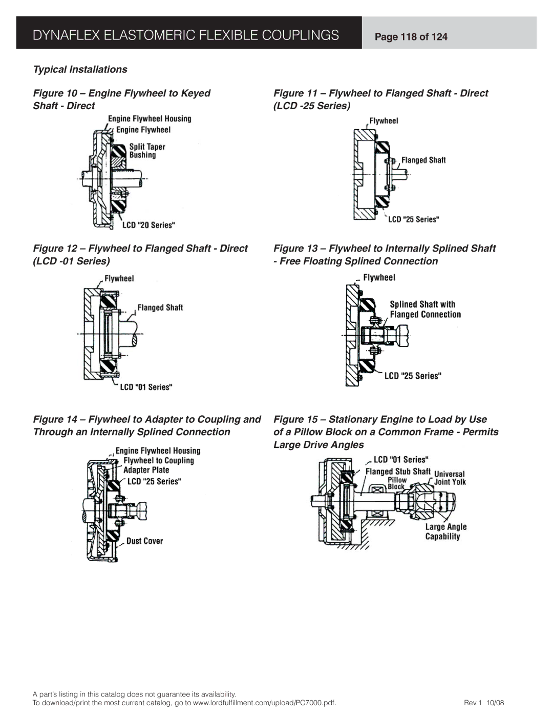
Typical Installations
Figure 10 – Engine Flywheel to Keyed Shaft - Direct
Figure 12 – Flywheel to Flanged Shaft - Direct (LCD -01 Series)
Figure 14 – Flywheel to Adapter to Coupling and Through an Internally Splined Connection
Figure 11 – Flywheel to Flanged Shaft - Direct (LCD -25 Series)
Figure 13 – Flywheel to Internally Splined Shaft - Free Floating Splined Connection
Figure 15 – Stationary Engine to Load by Use of a Pillow Block on a Common Frame - Permits Large Drive Angles
A part’s listing in this catalog does not guarantee its availability. |
|
To download/print the most current catalog, go to www.lordfulfi llment.com/upload/PC7000.pdf. | Rev.1 10/08 |
