DYNAFLEX ELASTOMERIC FLEXIBLE COUPLINGS Page 115 of 124
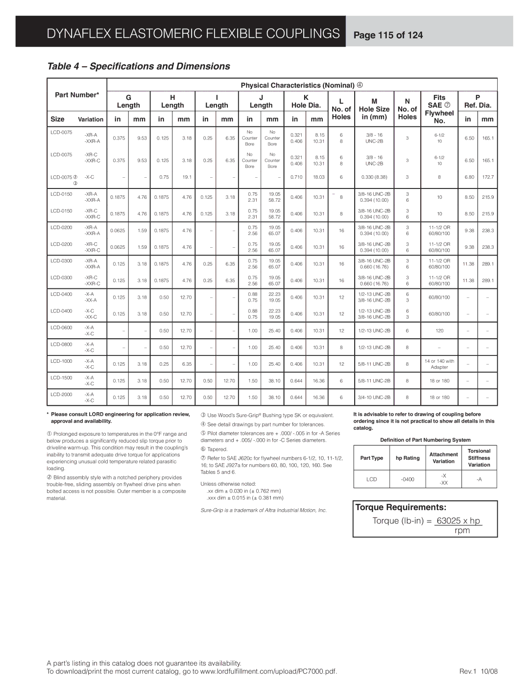
Table 4 – Specifications and Dimensions
|
|
|
|
|
|
|
|
|
| Physical Characteristics (Nominal) |
|
|
|
|
|
| ||||||
Part Number* |
|
|
|
|
|
|
|
|
|
|
|
|
|
|
|
|
|
|
|
|
| |
| G |
| H |
| I |
| J |
| K | L | M | N | Fits |
| P | |||||||
|
|
|
|
|
|
|
| |||||||||||||||
|
| Length | Length | Length | Length | Hole Dia. | SAE | Ref. Dia. | ||||||||||||||
|
| No. of | Hole Size | No. of | ||||||||||||||||||
|
|
|
|
|
|
|
|
|
|
|
|
|
|
|
| Flywheel |
|
|
| |||
Size | Variation | in |
| mm | in |
| mm | in | mm | in |
| mm | in |
| mm | Holes | in (mm) | Holes | in |
| mm | |
|
|
|
| No. |
| |||||||||||||||||
|
|
|
|
|
|
|
| |||||||||||||||
|
|
|
|
|
|
|
|
|
|
|
|
|
|
|
|
|
|
|
|
|
|
|
|
|
|
|
|
|
|
| No |
| No | 0.321 |
| 8.15 | 6 | 3/8 - 16 |
|
|
|
| |||
| 0.375 |
| 9.53 | 0.125 |
| 3.18 | 0.25 | 6.35 | Counter |
| Counter |
| 3 | 6.50 |
| 165.1 | ||||||
|
|
|
| 0.406 |
| 10.31 | 8 | 10 |
| |||||||||||||
|
|
|
|
|
|
|
|
| Bore |
| Bore |
|
|
|
|
| ||||||
|
|
|
|
|
|
|
|
|
|
|
|
|
|
|
|
|
|
|
|
| ||
|
|
|
|
|
|
|
| No |
| No | 0.321 |
| 8.15 | 6 | 3/8 - 16 |
|
|
|
| |||
|
| 0.375 |
| 9.53 | 0.125 |
| 3.18 | 0.25 | 6.35 | Counter |
| Counter |
| 3 | 6.50 |
| 165.1 | |||||
|
|
|
| 0.406 |
| 10.31 | 8 | 10 |
| |||||||||||||
|
|
|
|
|
|
|
|
|
| Bore |
| Bore |
|
|
|
|
| |||||
|
|
|
|
|
|
|
|
|
|
|
|
|
|
|
|
|
|
|
|
| ||
– |
| – | 0.75 |
| 19.1 | – | – | – |
| – | 0.710 |
| 18.03 | 6 | 0.330 (8.38) | 3 | 8 | 6.80 |
| 172.7 | ||
|
|
|
|
|
|
|
|
|
|
|
|
|
|
|
|
|
|
|
|
|
|
|
0.1875 |
| 4.76 | 0.1875 |
| 4.76 | 0.125 | 3.18 | 0.75 |
| 19.05 | 0.406 |
| 10.31 | – | 3 | 10 | 8.50 |
| 215.9 | |||
|
|
| 2.31 |
| 58.72 |
| 8 | 0.394 (10.00) | 6 |
| ||||||||||||
|
|
|
|
|
|
|
|
|
|
|
|
|
|
|
|
|
| |||||
0.1875 |
| 4.76 | 0.1875 |
| 4.76 | 0.125 | 3.18 | 0.75 |
| 19.05 | 0.406 |
| 10.31 | 8 | 3 | 10 | 8.50 |
| 215.9 | |||
|
|
|
| 2.31 |
| 58.72 |
| 0.394 (10.00) | 6 |
| ||||||||||||
|
|
|
|
|
|
|
|
|
|
|
|
|
|
|
|
|
| |||||
|
|
|
|
|
|
|
|
|
|
|
|
|
|
|
|
|
|
|
|
|
|
|
0.0625 |
| 1.59 | 0.1875 |
| 4.76 | – | – | 0.75 |
| 19.05 | 0.406 |
| 10.31 | 16 | 3 | 9.38 |
| 238.3 | ||||
|
|
| 2.56 |
| 65.07 |
| 0.394 (10.00) | 6 | 60/80/100 |
| ||||||||||||
|
|
|
|
|
|
|
|
|
|
|
|
|
|
|
|
| ||||||
0.0625 |
| 1.59 | 0.1875 |
| 4.76 | – | – | 0.75 |
| 19.05 | 0.406 |
| 10.31 | 16 | 3 | 9.38 |
| 238.3 | ||||
|
|
|
| 2.56 |
| 65.07 |
| 0.394 (10.00) | 6 | 60/80/100 |
| |||||||||||
|
|
|
|
|
|
|
|
|
|
|
|
|
|
|
|
| ||||||
|
|
|
|
|
|
|
|
|
|
|
|
|
|
|
|
|
|
|
|
|
|
|
0.125 |
| 3.18 | 0.1875 |
| 4.76 | 0.25 | 6.35 | 0.75 |
| 19.05 | 0.406 |
| 10.31 | 16 | 3 | 11.38 |
| 289.1 | ||||
|
|
| 2.56 |
| 65.07 |
| 0.660 (16.76) | 6 | 60/80/100 |
| ||||||||||||
|
|
|
|
|
|
|
|
|
|
|
|
|
|
|
|
| ||||||
0.125 |
| 3.18 | 0.1875 |
| 4.76 | 0.25 | 6.35 | 0.75 |
| 19.05 | 0.406 |
| 10.31 | 16 | 3 | 11.38 |
| 289.1 | ||||
|
|
|
| 2.56 |
| 65.07 |
| 0.660 (16.76) | 6 | 60/80/100 |
| |||||||||||
|
|
|
|
|
|
|
|
|
|
|
|
|
|
|
|
| ||||||
|
|
|
|
|
|
|
|
|
|
|
|
|
|
|
|
|
|
|
|
|
|
|
0.125 |
| 3.18 | 0.50 |
| 12.70 | – | – | 0.88 |
| 22.23 | 0.406 |
| 10.31 | 12 | 6 | 60/80/100 | – |
| – | |||
|
|
|
| 0.75 |
| 19.05 |
| 3 |
| |||||||||||||
|
|
|
|
|
|
|
|
|
|
|
|
|
|
|
|
|
| |||||
0.125 |
| 3.18 | 0.50 |
| 12.70 | – | – | 0.88 |
| 22.23 | 0.406 |
| 10.31 | 12 | 6 | 60/80/100 | – |
| – | |||
|
|
|
| 0.75 |
| 19.05 |
| 3 |
| |||||||||||||
|
|
|
|
|
|
|
|
|
|
|
|
|
|
|
|
|
| |||||
|
|
|
|
|
|
|
|
|
|
|
|
|
|
|
|
|
|
|
|
|
|
|
– |
| – | 0.50 |
| 12.70 | – | – | 1.00 |
| 25.40 | 0.406 |
| 10.31 | 12 | 6 | 120 | – |
| – | |||
|
|
|
|
|
| |||||||||||||||||
|
|
|
|
|
|
|
|
|
|
|
|
|
|
|
|
|
|
|
|
|
| |
|
|
|
|
|
|
|
|
|
|
|
|
|
|
|
|
|
|
|
|
|
|
|
– |
| – | 0.50 |
| 12.70 | – | – | 1.00 |
| 25.40 | 0.406 |
| 10.31 | 8 | 8 | – | – |
| – | |||
|
|
|
|
|
| |||||||||||||||||
|
|
|
|
|
|
|
|
|
|
|
|
|
|
|
|
|
|
|
|
|
| |
|
|
|
|
|
|
|
|
|
|
|
|
|
|
|
|
|
|
|
|
|
|
|
0.125 |
| 3.18 | 0.25 |
| 6.35 | – | – | 1.00 |
| 25.40 | 0.406 |
| 10.31 | 12 | 8 | 14 or 140 with | – |
| – | |||
|
|
|
|
| Adapter |
| ||||||||||||||||
|
|
|
|
|
|
|
|
|
|
|
|
|
|
|
|
|
|
|
|
| ||
|
|
|
|
|
|
|
|
|
|
|
|
|
|
|
|
|
|
|
|
|
|
|
0.125 |
| 3.18 | 0.50 |
| 12.70 | 0.50 | 12.70 | 1.50 |
| 38.10 | 0.644 |
| 16.36 | 6 | 8 | 18 or 180 | – |
| – | |||
|
|
|
|
|
| |||||||||||||||||
|
|
|
|
|
|
|
|
|
|
|
|
|
|
|
|
|
|
|
|
|
| |
|
|
|
|
|
|
|
|
|
|
|
|
|
|
|
|
|
|
|
|
|
|
|
0.125 |
| 3.18 | 0.50 |
| 12.70 | 0.50 | 12.70 | 1.50 |
| 38.10 | 0.644 |
| 16.36 | 6 | 8 | 18 or 180 | – |
| – | |||
|
|
|
|
|
| |||||||||||||||||
|
|
|
|
|
|
|
|
|
|
|
|
|
|
|
|
|
|
|
|
|
| |
|
|
|
|
|
|
|
|
|
|
|
|
|
|
|
|
|
|
|
|
|
|
|
*Please consult LORD engineering for application review, approval and availability.
Prolonged exposure to temperatures in the 0°F range and below produces a signifi cantly reduced slip torque prior to driveline
Blind assembly style with a notched periphery provides
Use Wood’s
See detail drawings by part number for tolerances.
Pilot diameter tolerances are + .000/
Tapered.
Refer to SAE J620c for fl ywheel numbers
Unless otherwise noted:
.xx dim ± 0.030 in (± 0.762 mm)
.xxx dim ± 0.015 in (± 0.381 mm)
It is advisable to refer to drawing of coupling before ordering since it is not practical to show all details in this catalog.
Definition of Part Numbering System
|
| Attachment | Torsional | |
Part Type | hp Rating | Stiffness | ||
Variation | ||||
|
| Variation | ||
|
|
| ||
|
|
|
| |
LCD | ||||
|
|
| ||
|
|
|
|
Torque Requirements:
Torque
A part’s listing in this catalog does not guarantee its availability. |
|
To download/print the most current catalog, go to www.lordfulfi llment.com/upload/PC7000.pdf. | Rev.1 10/08 |