Intelligent Technologies (IT.) QSNAP
February 2002
2.To lock the starter interface to the overload, rotate the orange locking tabs until the tab is locked into the slots in the overload. Use Figure 11 for information on which way to rotate the locking tabs.
Note: Refer to the IT. Contactor and Starter User Manual (Publication No. 49400) for more information on locking and unlocking the terminal block to the starter.
Connect the QSNAP to QCPort
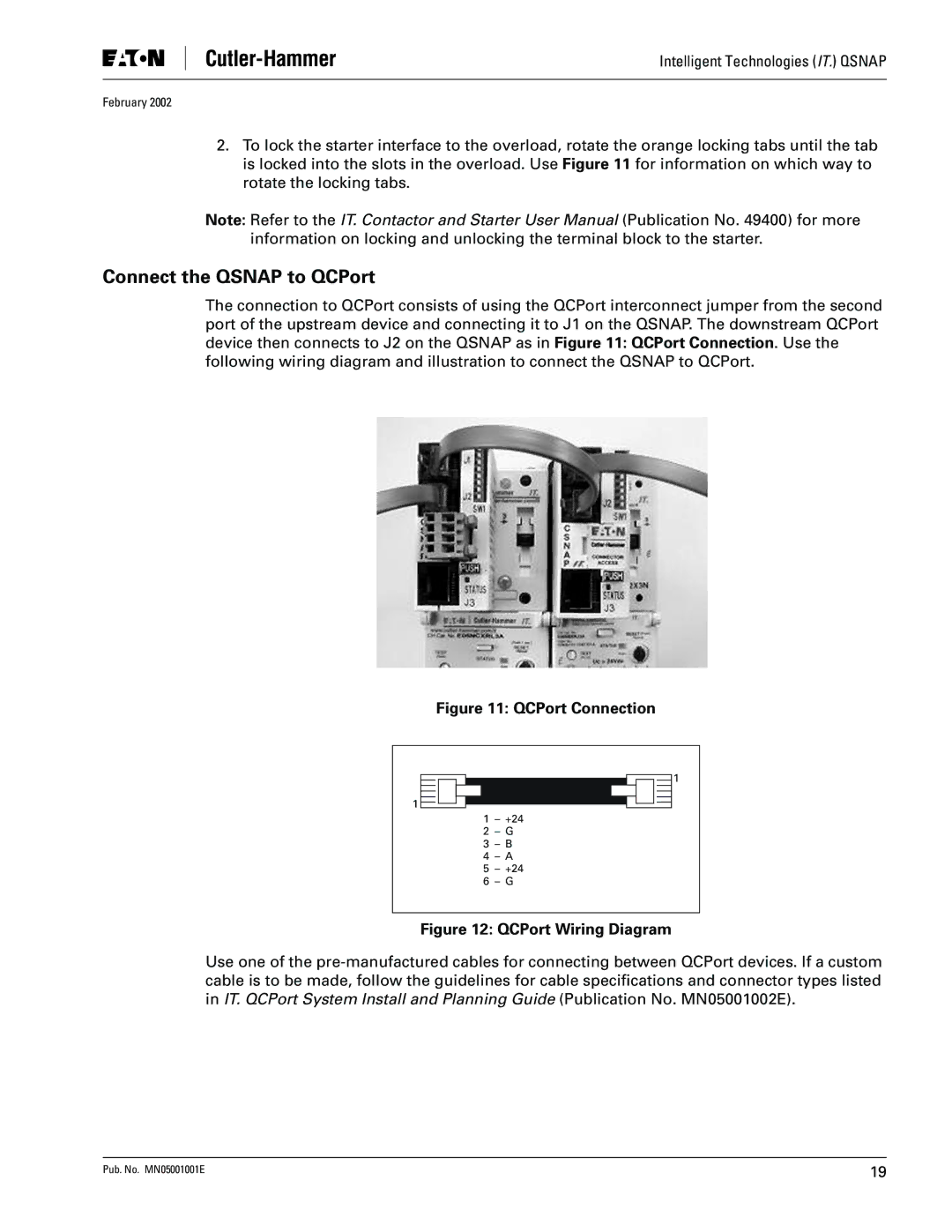
The connection to QCPort consists of using the QCPort interconnect jumper from the second port of the upstream device and connecting it to J1 on the QSNAP. The downstream QCPort device then connects to J2 on the QSNAP as in Figure 11: QCPort Connection. Use the following wiring diagram and illustration to connect the QSNAP to QCPort.
Figure 11: QCPort Connection
1
1 – +24
2 – G
3 – B
4 – A
5 – +24
6 – G
1
Figure 12: QCPort Wiring Diagram
Use one of the
Pub. No. MN05001001E | 19 |