EDGE 540. | Instruction Manual. |
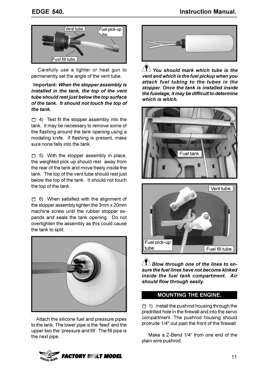
Vent tube. |
| Fuel |
|
| tube. |
Fuel fill tube.
Carefully use a lighter or heat gun to permenently set the angle of the vent tube.
Important: When the stopper assembly is installed in the tank, the top of the vent tube should rest just below the top surface of the tank. It should not touch the top of the tank.
4)Test fit the stopper assembly into the tank. It may be necessary to remove some of the flashing around the tank opening using a modeling knife. If flashing is present, make sure none falls into the tank.
5)With the stopper assembly in place, the weighted pick up should rest away from the rear of the tank and move freely inside the tank. The top of the vent tube should rest just below the top of the tank. It should not touch the top of the tank.
6)When satisfied with the alignment of the stopper assembly tighten the 3mm x 20mm machine screw until the rubber stopper ex- pands and seals the tank opening. Do not overtighten the assembly as this could cause the tank to split.
Attach the silicone fuel and pressure pipes to the tank. The lower pipe is the ‘feed’ and the upper two the ‘pressure and fill’. The fill pipe is the next pipe.
![]() You should mark which tube is the vent and which is the fuel pickup when you attach fuel tubing to the tubes in the stopper. Once the tank is installed inside the fuselage, it may be difficult to determine which is which.
You should mark which tube is the vent and which is the fuel pickup when you attach fuel tubing to the tubes in the stopper. Once the tank is installed inside the fuselage, it may be difficult to determine which is which.
Fuel tank.
Vent tube.
Fuel |
|
tube. | Fuel fill tube. |
![]() Blow through one of the lines to en- sure the fuel lines have not become kinked inside the fuel tank compartment. Air should flow through easily.
Blow through one of the lines to en- sure the fuel lines have not become kinked inside the fuel tank compartment. Air should flow through easily.
MOUNTING THE ENGINE.
1)Install the pushrod housing through the predrilled hole in the firewall and into the servo compartment. The pushrod housing should protrude 1/4" out past the front of the firewall.
Make a
11