Appendix
Configurations of Terminals
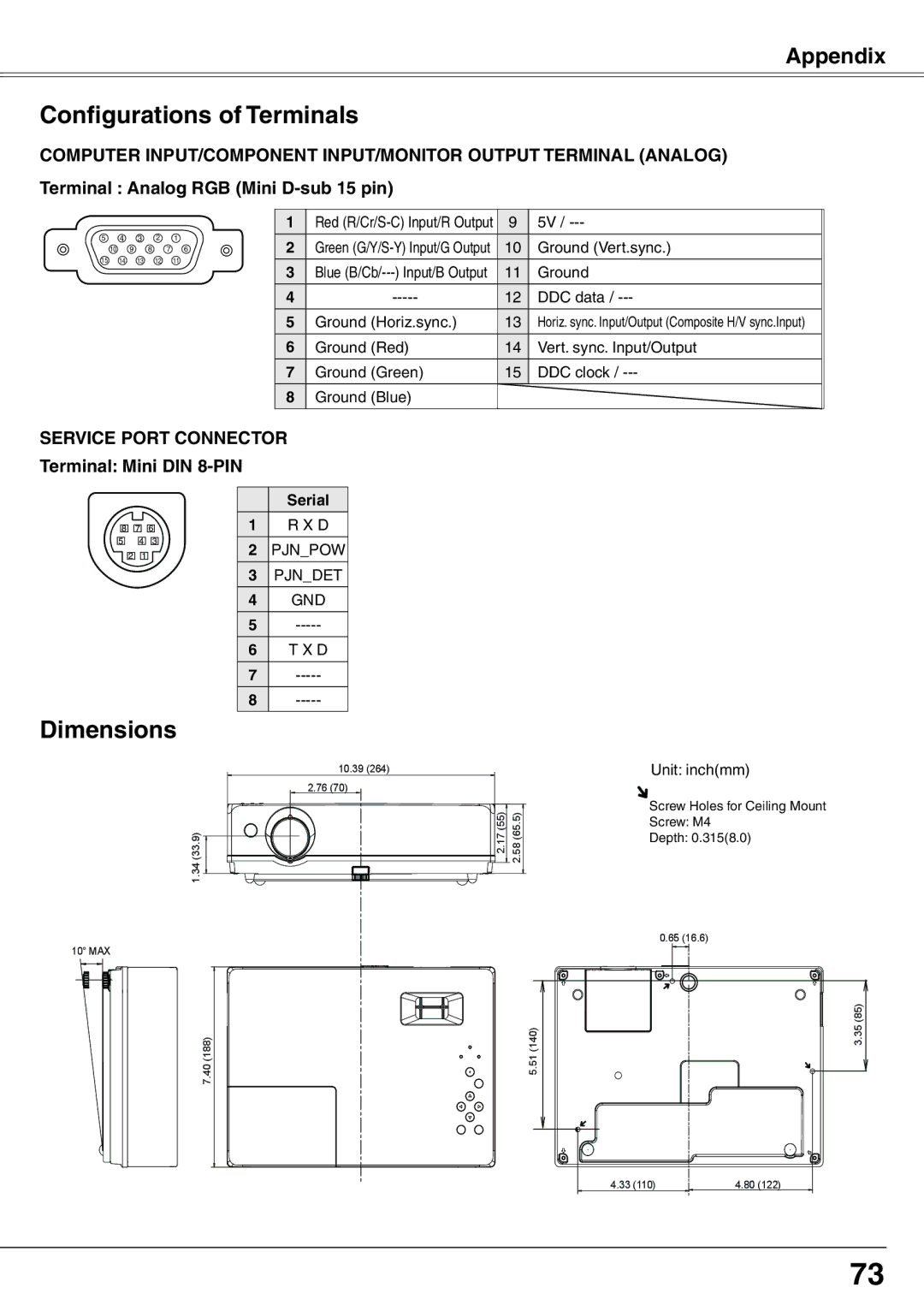
COMPUTER INPUT/COMPONENT INPUT/MONITOR OUTPUT TERMINAL (ANALOG) Terminal : Analog RGB (Mini
5 4 3 2 1
10 9 8 7 6
15 14 13 12 11
1 | Red | 9 | 5V / |
2 | Green | 10 | Ground (Vert.sync.) |
3 | Blue | 11 | Ground |
4 | 12 | DDC data / | |
5 | Ground (Horiz.sync.) | 13 | Horiz. sync. Input/Output (Composite H/V sync.Input) |
6 | Ground (Red) | 14 | Vert. sync. Input/Output |
7 | Ground (Green) | 15 | DDC clock / |
8 | Ground (Blue) |
|
|
|
|
|
|
SERVICE PORT CONNECTOR Terminal: Mini DIN 8-PIN
|
|
|
| Serial |
8 | 7 | 6 | 1 | R X D |
5 | 4 | 3 | 2 | PJN_POW |
2 | 1 |
| ||
|
|
| 3 | PJN_DET |
|
|
| 4 | GND |
|
|
| 5 | |
|
|
| 6 | T X D |
|
|
| 7 | |
|
|
| 8 | |
|
|
|
|
|
Dimensions
1.34 (33.9)
10˚ MAX
7.40 (188)
10.39 (264) |
|
2.76 (70) |
|
2.17 (55) | 2.58 (65.5) |
Unit: inch(mm)
Screw Holes for Ceiling Mount
Screw: M4
Depth: 0.315(8.0)
| 0.65 (16.6) |
(140) | 3.35 (85) |
5.51 |
|
4.33 (110) | 4.80 (122) |
73
