Speaker System specifications
Electro-Voice, a brand renowned for its high-quality audio solutions, has long been a pioneer in the speaker system market. The Electro-Voice Speaker System offers a diverse array of products designed to cater to a multitude of audio needs, from professional touring to installation in venues and home use.One of the standout features of the Electro-Voice speaker systems is their innovative design, which combines durability with aesthetic appeal. Constructed with rugged, weather-resistant materials, they are built to withstand the rigors of touring while maintaining exceptional performance in various environments. This makes them a popular choice for live sound engineers and musicians alike.
In terms of sound quality, Electro-Voice speakers utilize advanced technologies such as the patented Constant Directivity Horns, which provide broad coverage and minimize distortion. This is particularly crucial in larger venues, where maintaining clarity and presence can be a challenge. The use of high-performance transducers ensures that the audio output is balanced across all frequencies, delivering crisp highs, rich mids, and powerful lows.
Another impressive characteristic is the intelligent integration of digital signal processing (DSP) in many of their systems. This technology allows for precise control over sound customization, enabling users to tune their speakers for specific applications or venue acoustics. The DSP capabilities help optimize sound quality while protecting the system from potential damage due to overdrive or feedback.
Portability is another key aspect of the Electro-Voice speaker system lineup. Many models are designed to be lightweight and easy to transport, allowing for quick setup and takedown, making them ideal for mobile DJs and bands. Moreover, the flexible rigging options available with multiple models ensure that users can adapt the speakers' positioning to maximize sound performance.
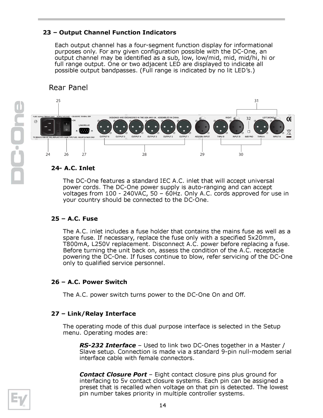
Electro-Voice also emphasizes connectivity with modern audio systems. Many of their speakers are equipped with versatile input options, making them compatible with various mixing consoles, amplifiers, and other sound equipment. This flexibility simplifies integration into existing setups and enhances usability across different scenarios.
Additionally, the aesthetic design of Electro-Voice speakers, often featuring sleek lines and contemporary finishes, allows them to blend seamlessly into a variety of environments, from high-end venues to casual settings.
Overall, the Electro-Voice speaker system stands out for its combination of robust construction, superior sound quality, advanced technology, portability, and versatile connectivity options. Whether for professional sound reinforcement or personal audio enjoyment, these systems facilitate a remarkable audio experience that has become synonymous with the Electro-Voice brand.

