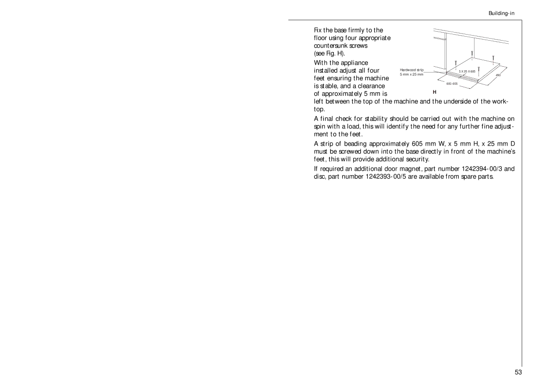
Fix the base firmly to the floor using four appropriate countersunk screws
(see Fig. H).
With the appliance
installed adjust all four | Hardwood strip | 5 X 25 X 605 | |
5 mm x 25 mm | |||
feet ensuring the machine | 490 | ||
|
| ||
is stable, and a clearance |
| ||
| H | ||
of approximately 5 mm is |
|
left between the top of the machine and the underside of the work- top.
A final check for stability should be carried out with the machine on spin with a load, this will identify the need for any further fine adjust- ment to the feet.
A strip of beading approximately 605 mm W, x 5 mm H, x 25 mm D must be screwed down into the base directly in front of the machine’s feet, this will provide additional security.
If required an additional door magnet, part number
53