USA
4. ELECTRICAL CONNECTION
•A fused disconnect switch or main circuit breaker (customer furnished) MUST be installed in the electric supply line for the appliance. It is recommended that this switch/circuit breaker have lockout/tagout capability. Before making any electrical connections to this appliance, check that the power supply is adequate for the voltage, amperage, and phase requirements on the rating plate.
•A safety cutout switch of suitable capacity with a contact breaking distance of at least 3 mm must be fitted upstream of the appliance.
The cutout switch must be installed near the appliance in the permanent electrical system of the premises.
•The appliance must be electrically grounded in accordance with local codes, or in the absence of local codes, with the National Electrical Code, ANSI/NFPA 70, or the Canadian Electrical Code, CSA C22.2, as applicable.
The grounding conductor must therefore be connected to the terminal marked Gon the connection terminal board. The appliance must also be connected to an earth grounding system.
This connection is made using the stop screw marked E located on the outside of the appliance near the power cable inlet.
The grounding wire must have a minimum cross-section of 8 AWG (10 mm2).
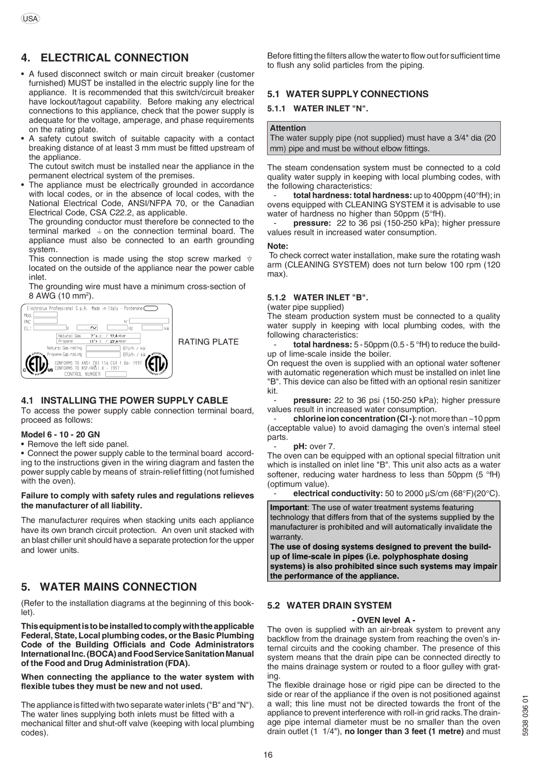
RATING PLATE
4.1 INSTALLING THE POWER SUPPLY CABLE
To access the power supply cable connection terminal board, proceed as follows:
Model 6 - 10 - 20 GN
•Remove the left side panel.
•Connect the power supply cable to the terminal board accord- ing to the instructions given in the wiring diagram and fasten the power supply cable by means of strain-relief fitting (not furnished with the oven).
Failure to comply with safety rules and regulations relieves the manufacturer of all liability.
The manufacturer requires when stacking units each appliance have its own branch circuit protection. An oven unit stacked with an blast chiller unit should have a separate protection for the upper and lower units.
5. WATER MAINS CONNECTION
(Refer to the installation diagrams at the beginning of this book- let).
This equipment is to be installed to comply with the applicable Federal, State, Local plumbing codes, or the Basic Plumbing Code of the Building Officials and Code Administrators International Inc. (BOCA) and Food Service Sanitation Manual of the Food and Drug Administration (FDA).
When connecting the appliance to the water system with flexible tubes they must be new and not used.
The appliance is fitted with two separate water inlets ("B" and "N"). The water lines supplying both inlets must be fitted with a mechanical filter and shut-off valve (keeping with local plumbing codes).
Before fitting the filters allow the water to flow out for sufficient time to flush any solid particles from the piping.
5.1 WATER SUPPLY CONNECTIONS
5.1.1 WATER INLET "N".
Attention
The water supply pipe (not supplied) must have a 3/4" dia (20 mm) pipe and must be without elbow fittings.
The steam condensation system must be connected to a cold quality water supply in keeping with local plumbing codes, with the following characteristics:
-total hardness: total hardness: up to 400ppm (40°fH); in ovens equipped with CLEANING SYSTEM it is advisable to use water of hardness no higher than 50ppm (5°fH).
-pressure: 22 to 36 psi (150-250 kPa); higher pressure values result in increased water consumption.
Note:
To check correct water installation, make sure the rotating wash arm (CLEANING SYSTEM) does not turn below 100 rpm (120 max).
5.1.2WATER INLET "B". (water pipe supplied)
The steam production system must be connected to a quality water supply in keeping with local plumbing codes, with the following characteristics:
- total hardness: 5 - 50ppm (0.5 - 5 °fH) to reduce the build- up of lime-scale inside the boiler.
On request the oven is supplied with an optional water softener with automatic regeneration which must be installed on inlet line "B". This device can also be fitted with an optional resin sanitizer kit.
- pressure: 22 to 36 psi (150-250 kPa); higher pressure values result in increased water consumption.
- chlorine ion concentration (Cl -): not more than ~10 ppm (acceptable value) to avoid damaging the oven's internal steel parts.
- pH: over 7.
The oven can be equipped with an optional special filtration unit which is installed on inlet line "B". This unit also acts as a water softener, reducing water hardness to less than 50ppm (5 °fH) (optimum value).
- electrical conductivity: 50 to 2000 µS/cm (68°F)(20°C).
Important: The use of water treatment systems featuring technology that differs from that of the systems supplied by the manufacturer is prohibited and will automatically invalidate the warranty.
The use of dosing systems designed to prevent the build- up of lime-scale in pipes (i.e. polyphosphate dosing systems) is also prohibited since such systems may impair the performance of the appliance.
5.2 WATER DRAIN SYSTEM
- OVEN level A -
The oven is supplied with an air-break system to prevent any backflow from the drainage system from reaching the oven’s in- ternal circuits and the cooking chamber. The presence of this system means that the drain pipe can be connected directly to the mains drainage system or routed to a floor gulley with grat- ing.
The flexible drainage hose or rigid pipe can be directed to the side or rear of the appliance if the oven is not positioned against a wall; this line must not be directed towards the front of the appliance to prevent interference with roll-in grid racks.The drain- age pipe internal diameter must be no smaller than the oven drain outlet (1 1/4"), no longer than 3 feet (1 metre) and must