Connection to the monitor and the projector
The following settings of the Presenter can be switched with the DIP switch. Switch the settings according to the connection environment. The factory settings are as shown in the following table:
Key | Function | Initial setting | ||
Key selection | Content | |||
|
| |||
A | To switch the image output | 0 | SXGA output | |
B | To switch the TV output method | 0 | NTSC | |
|
|
|
| |
C | To switch the TV output screen size | 0 | Over scan | |
|
|
|
| |
D | To initialize the network function settings | 0 | Normal operation | |
Note: Be sure to turn OFF the power supply to all equipment before making any connections to protect the Presenter and all the connected equipment.
Note: When switching the I/O selection switch key, be sure to turn OFF the power supply to the Presenter beforehand.
Note: Hold the cable plug when connecting or disconnecting the cables.
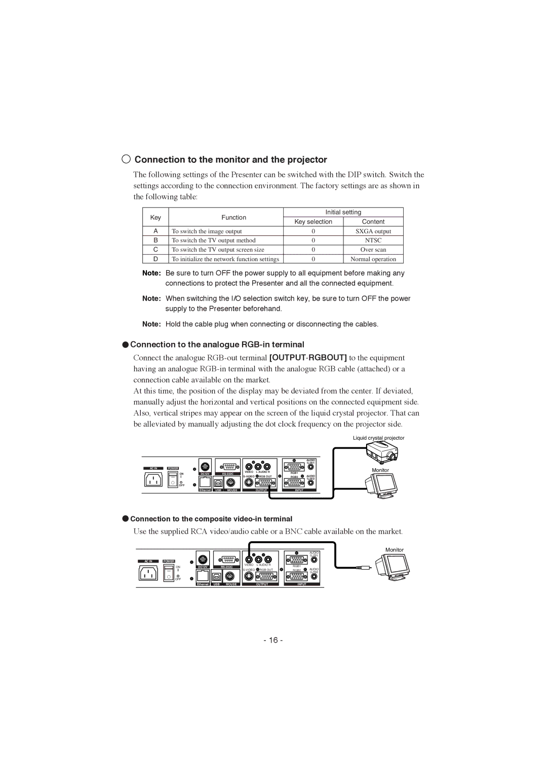
 Connection to the analogue
 RGB-in terminal
Connect the analogue
At this time, the position of the display may be deviated from the center. If deviated, manually adjust the horizontal and vertical positions on the connected equipment side. Also, vertical stripes may appear on the screen of the liquid crystal projector. That can be alleviated by manually adjusting the dot clock frequency on the projector side.
Liquid crystal projector
AC IN |
| POWER |
ON
OFF
DC12VRS-232C
Ethernet USB MOUSE
VIDEO L AUDIO R ![]() RGB OUT
RGB OUT
OUTPUT
AUDIO
(L/R)1
RGB1 | AUDIO |
RGB2 | |
| (L/R)2 |
INPUT |
|
Monitor
 Connection to the composite
 video-in terminal
Use the supplied RCA video/audio cable or a BNC cable available on the market.
AC IN |
| POWER |
ON
OFF
DC12VRS-232C
Ethernet USB MOUSE
VIDEO L AUDIO R
![]() RGB OUT
RGB OUT
OUTPUT
AUDIO
(L/R)1
RGB1 | AUDIO | |
RGB2 | ||
(L/R)2 | ||
| ||
INPUT |
|
Monitor
- 16 -