Quick Installation Guide
Smart Wireless THUM Adapter
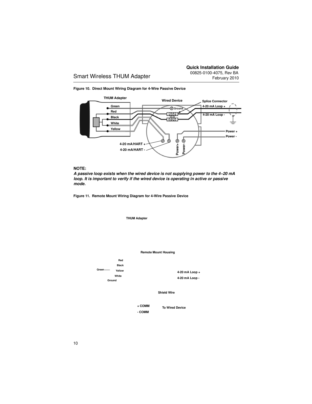
Figure 10. Direct Mount Wiring Diagram for 4-Wire Passive Device
THUM Adapter
Green
Red
Black
White
Yellow
![]()
Wired Device | Splice Connector |
Ground | |
| |
| |
| Power + |
| Power - |
Power+ Power- |
|
NOTE:
A passive loop exists when the wired device is not supplying power to the
Figure 11. Remote Mount Wiring Diagram for 4-Wire Passive Device
THUM Adapter
Remote Mount Housing
Red
Black
Green |
| Yellow |
| |
|
| |||
|
|
| ||
|
| White |
| |
|
|
| ||
| Ground |
| ||
|
|
| ||
|
|
|
| Shield Wire |
|
|
| + COMM | To Wired Device |
|
|
|
| |
|
|
| - COMM |
|
10