Quick Installation Guide
Smart Wireless THUM Adapter
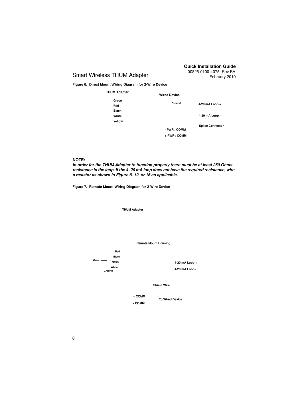
Figure 6. Direct Mount Wiring Diagram for 2-Wire Device
THUM Adapter | Wired Device |
| |
|
| ||
Green | Ground | ||
Red | |||
|
| ||
Black |
|
| |
White |
| ||
Yellow |
|
| |
| - PWR / COMM | Splice Connector | |
|
| ||
| + PWR / COMM |
|
NOTE:
In order for the THUM Adapter to function properly there must be at least 250 Ohms resistance in the loop. If the
Figure 7. Remote Mount Wiring Diagram for 2-Wire Device
THUM Adapter
|
|
| Remote Mount Housing |
|
| Red |
|
|
| Black |
|
Green |
| Yellow | |
| |||
|
| ||
|
| White | |
| Ground | ||
|
| ||
|
|
| Shield Wire |
|
|
| + COMM |
|
|
| To Wired Device |
|
|
| - COMM |
8