Quick Installation Guide
Smart Wireless THUM Adapter
Power Supply
Minimum loop load of 250 Ohms.
The THUM Adapter communicates via and derives power from a standard
The THUM Adapter will not affect the
Limit the power supply to 0.5 Amps maximum, and voltage to 55 Volts DC.
|
|
Loop Current | THUM Adapter voltage drop |
3.5 mA | 2.25 V |
25 mA | 1.2 V |
Load Resistor
If required, add a load resistor as shown in Figure 8, 12, and 16. The resistor should be adequately rated for the application (1W minimum) and be compatible with the supplied splice connector which accepts wire sizes from 14 to 22 AWG.
BENCH TOP CONFIGURATION
When performing bench top configuration it is suggested that you connect the THUM Adapter to a wired device. If this is not possible the following wiring diagrams can be used. For bench top configuration ensure that the power supply that you are using is limited to 0.5 Amps maximum.
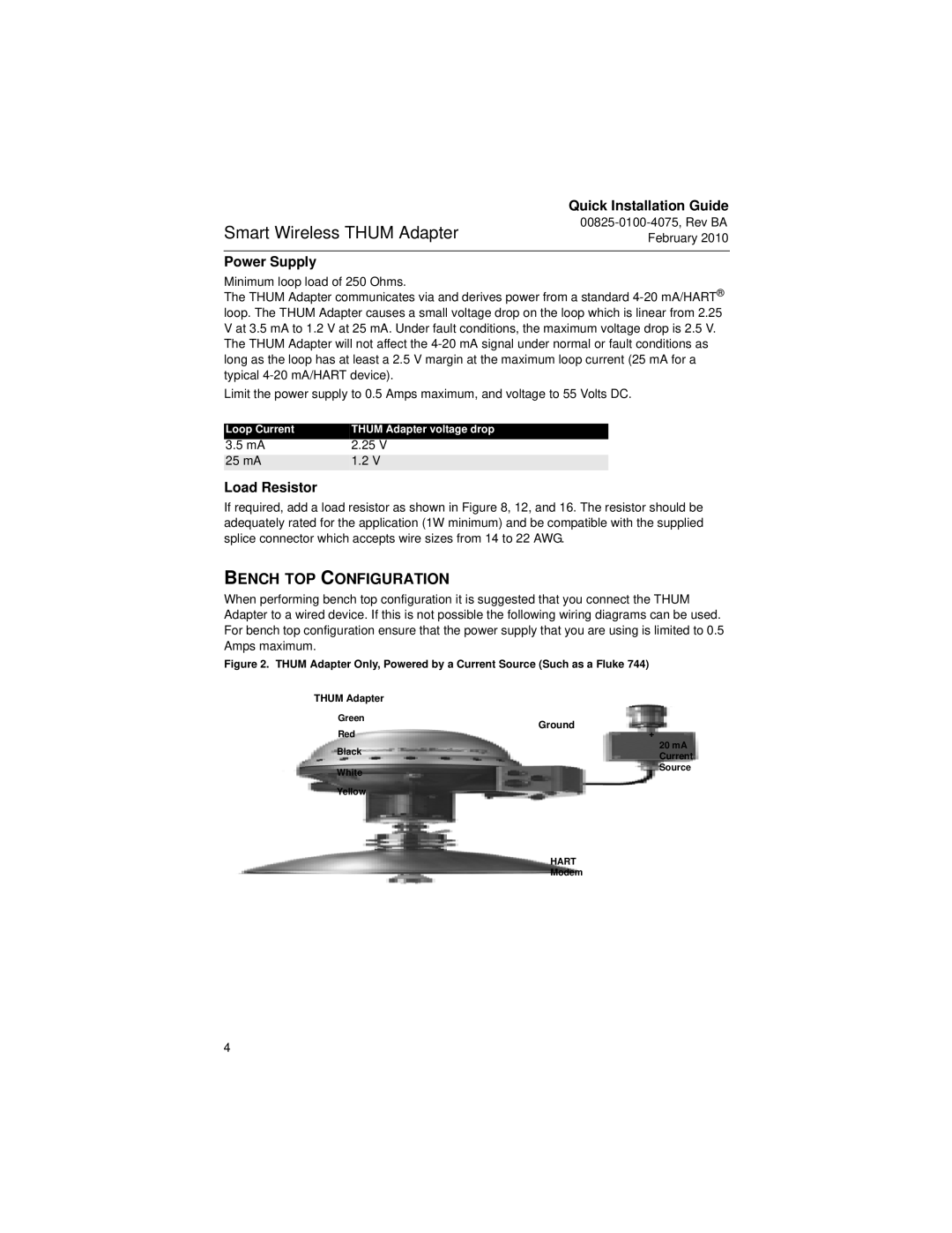
Figure 2. THUM Adapter Only, Powered by a Current Source (Such as a Fluke 744)
THUM Adapter
Green | Ground | |
Red | ||
+ | ||
Black | 20 mA | |
Current | ||
| ||
White | - Source | |
Yellow |
| |
| HART | |
| Modem |
4