26Chapter 1 Overview
Central office alarms
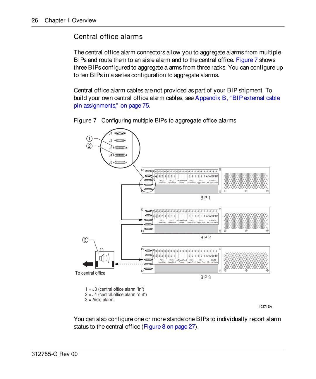
The central office alarm connectors allow you to aggregate alarms from multiple BIPs and route them to an aisle alarm and to the central office. Figure 7 shows three BIPs configured to aggregate alarms from three racks. You can configure up to ten BIPs in a series configuration to aggregate alarms.
Central office alarm cables are not provided as part of your BIP shipment. To build your own central office alarm cables, see Appendix B, “BIP external cable pin assignments,” on page 75.
Figure 7 Configuring multiple BIPs to aggregate office alarms
1
2
J1
J2
J3 ![]()
![]()
![]()
J4 ![]()
![]()
![]()
J5 ![]()
![]()
![]()
3 2 1 3 2 1 |
| 3 2 1 3 2 1 A1 A2 B1 B2 | |||
PS (+) | PS (+) | A/B Input Feed | PS | PS | – 48 VDC |
Lower Shelf | Upper Shelf | Returns | Lower Shelf | Upper Shelf | A/B Input Feeds |
BIP 1


 3 2 1 3 2 1
3 2 1 3 2 1 A1 A2 B1 B2
PS (+) | PS (+) A/B Input Feed | PS | PS | – 48 VDC | |
Lower Shelf | Upper Shelf | Returns | Lower Shelf | Upper Shelf | A/B Input Feeds |
|
|
|
|
|
|
|
|
|
|
|
|
3 |
|
|
| BIP 2 | |
|
|
|
|
| |
3 2 1 3 2 1 |
| 3 2 1 3 2 1 A1 A2 B1 B2 | |||
PS (+) | PS (+) | A/B Input Feed | PS | PS | – 48 VDC |
Lower Shelf | Upper Shelf | Returns | Lower Shelf | Upper Shelf | A/B Input Feeds |
To central office
BIP 3
1 = J3 (central office alarm "in")
2 = J4 (central office alarm "out")
3 = Aisle alarm
10371EA
You can also configure one or more standalone BIPs to individually report alarm status to the central office (Figure 8 on page 27).