![](/images/new-backgrounds/1266168/26616889x1.webp)
Chapter 2 Installation 45
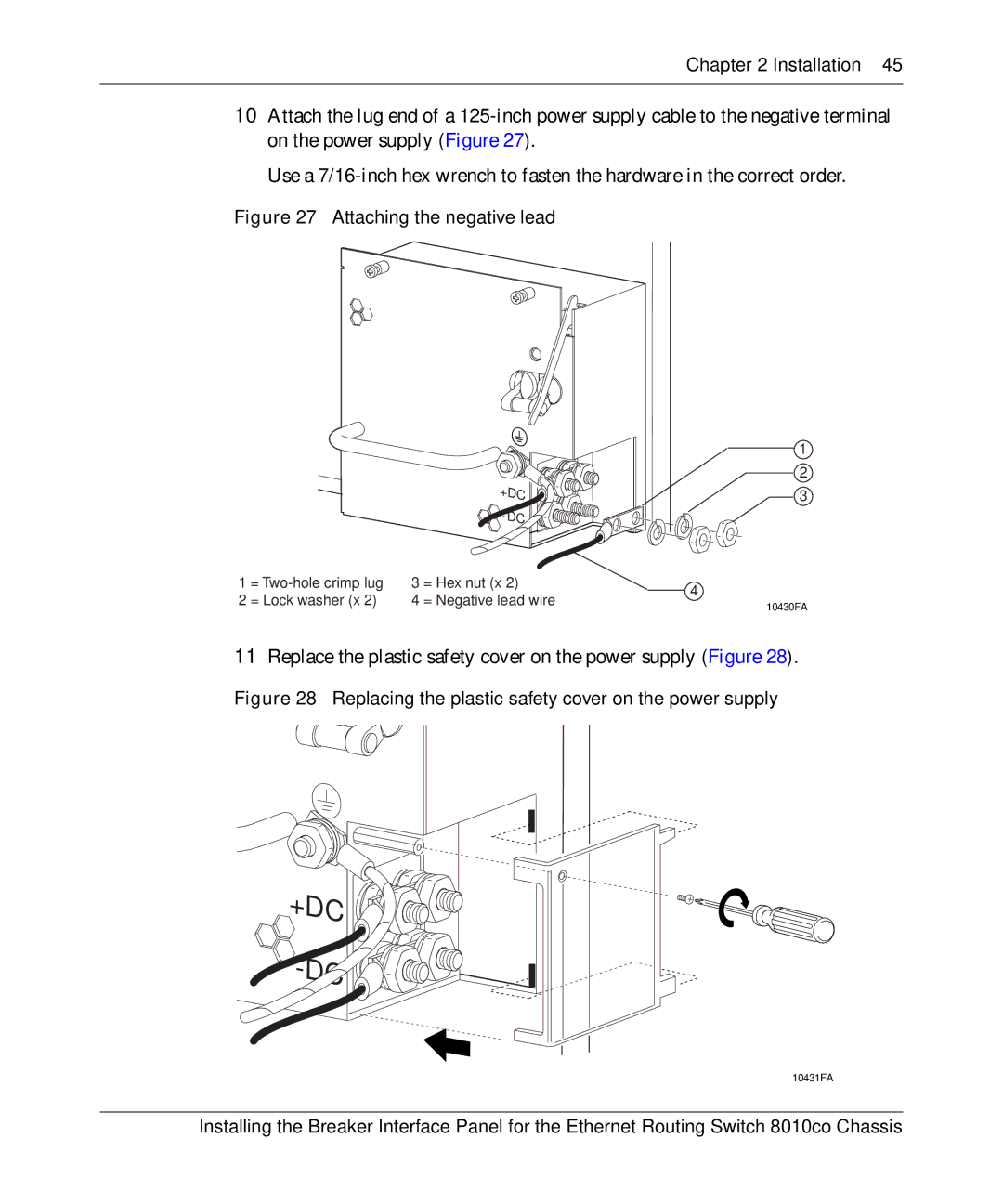
10Attach the lug end of a
Use a
Figure 27 Attaching the negative lead
|
|
|
| 1 | |
|
|
|
| 2 | |
|
|
| +DC | 3 | |
|
|
|
| ||
|
|
|
| ||
1 | = | 3 | = Hex nut (x 2) | 4 | |
2 | = Lock washer (x 2) | 4 | = Negative lead wire | ||
10430FA | |||||
|
|
|
|
11Replace the plastic safety cover on the power supply (Figure 28).
Figure 28 Replacing the plastic safety cover on the power supply
+DC ![](/images/new-backgrounds/1266168/26616889xi2.webp)
![](/images/new-backgrounds/1266168/26616889xi3.webp)
![](/images/new-backgrounds/1266168/26616889xi4.webp)
![](/images/new-backgrounds/1266168/26616889xi5.webp)
![](/images/new-backgrounds/1266168/26616889xi6.webp)
![](/images/new-backgrounds/1266168/26616889xi7.webp)
![](/images/new-backgrounds/1266168/26616889xi8.webp)
![](/images/new-backgrounds/1266168/26616889xi9.webp)
![](/images/new-backgrounds/1266168/26616889xi10.webp)
-DC ![](/images/new-backgrounds/1266168/26616889xi12.webp)
![](/images/new-backgrounds/1266168/26616889xi13.webp)
![](/images/new-backgrounds/1266168/26616889xi14.webp)
![](/images/new-backgrounds/1266168/26616889xi15.webp)
![](/images/new-backgrounds/1266168/26616889xi16.webp)
![](/images/new-backgrounds/1266168/26616889xi17.webp)
![](/images/new-backgrounds/1266168/26616889xi18.webp)
![](/images/new-backgrounds/1266168/26616889xi19.webp)
![](/images/new-backgrounds/1266168/26616889xi20.webp)
10431FA
Installing the Breaker Interface Panel for the Ethernet Routing Switch 8010co Chassis