22Chapter 1 Overview
Alarm module display panel
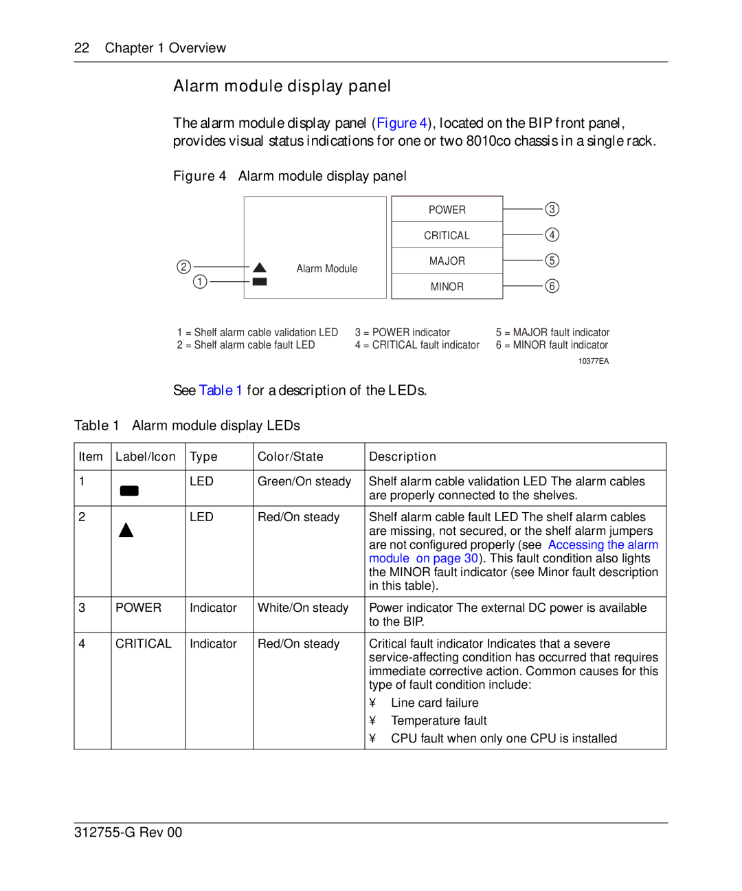
The alarm module display panel (Figure 4), located on the BIP front panel, provides visual status indications for one or two 8010co chassis in a single rack.
Figure 4 Alarm module display panel
|
| POWER |
|
| CRITICAL |
2 |
| MAJOR |
| Alarm Module | |
| 1 | MINOR |
|
|
3
4
5
6
1 | = Shelf alarm cable validation LED | 3 | = POWER indicator | 5 | = MAJOR fault indicator |
2 | = Shelf alarm cable fault LED | 4 | = CRITICAL fault indicator | 6 | = MINOR fault indicator |
|
|
|
|
| 10377EA |
See Table 1 for a description of the LEDs.
Table 1 Alarm module display LEDs
Item | Label/Icon | Type | Color/State | Description | |
|
|
|
|
| |
1 |
| LED | Green/On steady | Shelf alarm cable validation | |
|
|
|
| are properly connected to the shelves. | |
|
|
|
|
| |
2 |
| LED | Red/On steady | Shelf alarm cable fault | |
|
|
|
| are missing, not secured, or the shelf alarm jumpers | |
|
|
|
| are not configured properly (see “Accessing the alarm | |
|
|
|
| module” on page 30). This fault condition also lights | |
|
|
|
| the MINOR fault indicator (see Minor fault description | |
|
|
|
| in this table). | |
|
|
|
|
| |
3 | POWER | Indicator | White/On steady | Power | |
|
|
|
| to the BIP. | |
|
|
|
|
| |
4 | CRITICAL | Indicator | Red/On steady | Critical fault | |
|
|
|
| ||
|
|
|
| immediate corrective action. Common causes for this | |
|
|
|
| type of fault condition include: | |
|
|
|
| • | Line card failure |
|
|
|
| • | Temperature fault |
|
|
|
| • CPU fault when only one CPU is installed | |
|
|
|
|
|
|