|
|
|
| Chapter 1 Overview 23 |
|
|
|
|
|
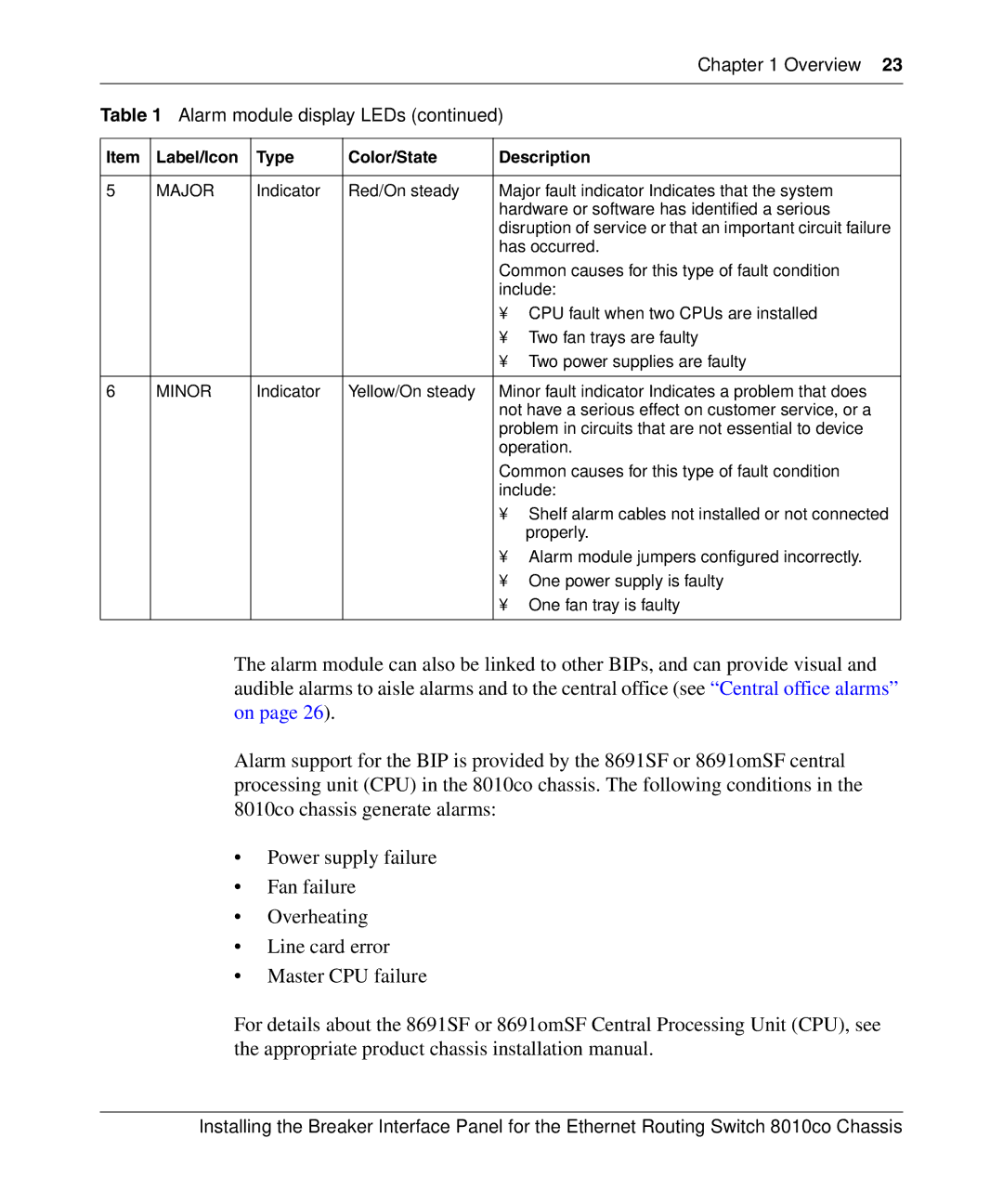
Table 1 Alarm module display LEDs (continued) | ||||
|
|
|
|
|
Item | Label/Icon | Type | Color/State | Description |
|
|
|
|
|
5 | MAJOR | Indicator | Red/On steady | Major fault |
|
|
|
| hardware or software has identified a serious |
|
|
|
| disruption of service or that an important circuit failure |
|
|
|
| has occurred. |
|
|
|
| Common causes for this type of fault condition |
|
|
|
| include: |
|
|
|
| • CPU fault when two CPUs are installed |
|
|
|
| • Two fan trays are faulty |
|
|
|
| • Two power supplies are faulty |
|
|
|
|
|
6 | MINOR | Indicator | Yellow/On steady | Minor fault |
|
|
|
| not have a serious effect on customer service, or a |
|
|
|
| problem in circuits that are not essential to device |
|
|
|
| operation. |
|
|
|
| Common causes for this type of fault condition |
|
|
|
| include: |
|
|
|
| • Shelf alarm cables not installed or not connected |
|
|
|
| properly. |
|
|
|
| • Alarm module jumpers configured incorrectly. |
|
|
|
| • One power supply is faulty |
|
|
|
| • One fan tray is faulty |
|
|
|
|
|
The alarm module can also be linked to other BIPs, and can provide visual and audible alarms to aisle alarms and to the central office (see “Central office alarms” on page 26).
Alarm support for the BIP is provided by the 8691SF or 8691omSF central processing unit (CPU) in the 8010co chassis. The following conditions in the 8010co chassis generate alarms:
•Power supply failure
•Fan failure
•Overheating
•Line card error
•Master CPU failure
For details about the 8691SF or 8691omSF Central Processing Unit (CPU), see the appropriate product chassis installation manual.
Installing the Breaker Interface Panel for the Ethernet Routing Switch 8010co Chassis