72Chapter 3 Problem solving
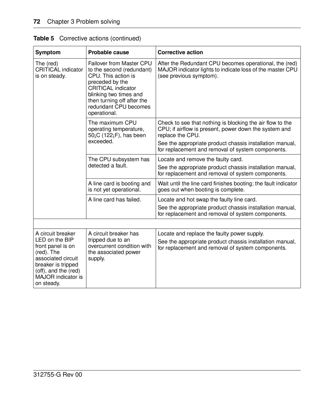
Table 5 Corrective actions (continued)
Symptom | Probable cause | Corrective action | |
|
|
| |
The (red) | Failover from Master CPU | After the Redundant CPU becomes operational, the (red) | |
CRITICAL indicator | to the second (redundant) | MAJOR indicator lights to indicate loss of the master CPU | |
is on steady. | CPU. This action is | (see previous symptom). | |
| preceded by the |
| |
| CRITICAL indicator |
| |
| blinking two times and |
| |
| then turning off after the |
| |
| redundant CPU becomes |
| |
| operational. |
| |
|
|
| |
| The maximum CPU | Check to see that nothing is blocking the air flow to the | |
| operating temperature, | CPU; if airflow is present, power down the system and | |
| 50°C (122°F), has been | replace the CPU. | |
| exceeded. | See the appropriate product chassis installation manual, | |
|
| ||
|
| for replacement and removal of system components. | |
|
|
| |
| The CPU subsystem has | Locate and remove the faulty card. | |
| detected a fault. | See the appropriate product chassis installation manual, | |
|
| ||
|
| for replacement and removal of system components. | |
|
|
| |
| A line card is booting and | Wait until the line card finishes booting; the fault indicator | |
| is not yet operational. | goes out when booting is complete. | |
|
|
| |
| A line card has failed. | Locate and hot swap the faulty line card. | |
|
| See the appropriate product chassis installation manual, | |
|
| for replacement and removal of system components. | |
|
|
| |
|
|
| |
A circuit breaker | A circuit breaker has | Locate and replace the faulty power supply. | |
LED on the BIP | tripped due to an | See the appropriate product chassis installation manual, | |
front panel is on | overcurrent condition with | ||
for replacement and removal of system components. | |||
(red). The | the associated power | ||
| |||
associated circuit | supply. |
| |
breaker is tripped |
|
| |
(off), and the (red) |
|
| |
MAJOR indicator is |
|
| |
on steady. |
|
| |
|
|
|
