42Chapter 2 Installation
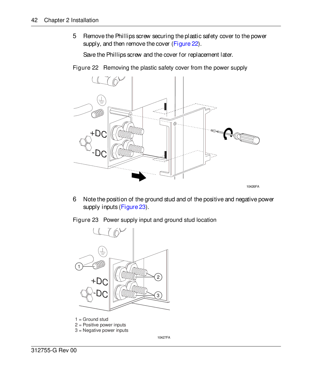
5Remove the Phillips screw securing the plastic safety cover to the power supply, and then remove the cover (Figure 22).
Save the Phillips screw and the cover for replacement later.
Figure 22 Removing the plastic safety cover from the power supply
+DC 


-DC 


10426FA
6Note the position of the ground stud and of the positive and negative power supply inputs (Figure 23).
Figure 23 Power supply input and ground stud location
1
+DC -DC
1 = Ground stud
2 = Positive power inputs
3 = Negative power inputs
2
3
10427FA
