Chapter 2 Installation 41
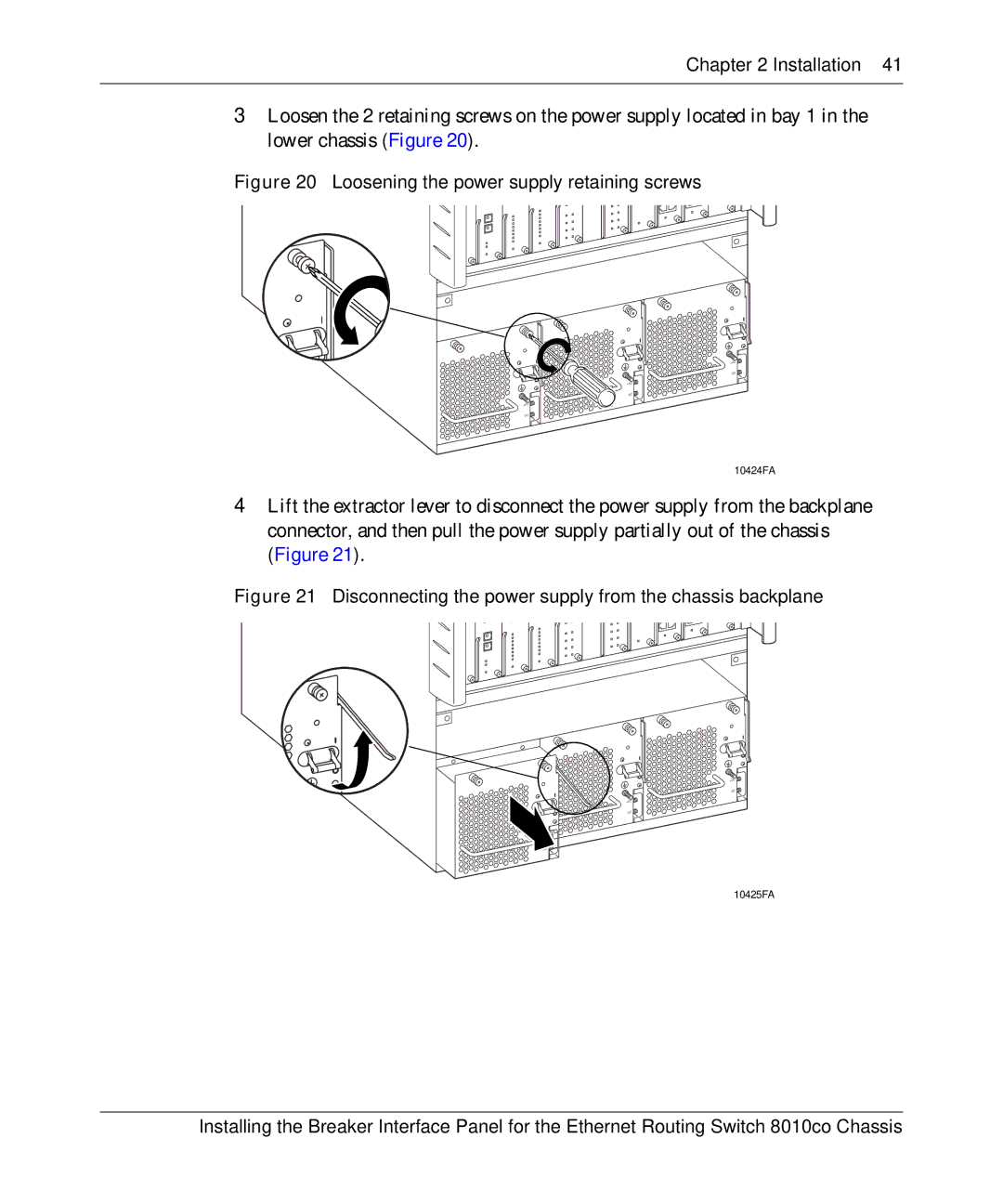
3Loosen the 2 retaining screws on the power supply located in bay 1 in the lower chassis (Figure 20).
Figure 20 Loosening the power supply retaining screws
+DC
![]()
+DC
![]()
+DC
![]()
10424FA
4Lift the extractor lever to disconnect the power supply from the backplane connector, and then pull the power supply partially out of the chassis (Figure 21).
Figure 21 Disconnecting the power supply from the chassis backplane
+DC
![]()
+DC
![]()
![]()
10425FA
Installing the Breaker Interface Panel for the Ethernet Routing Switch 8010co Chassis