Chapter 2 Installation 53
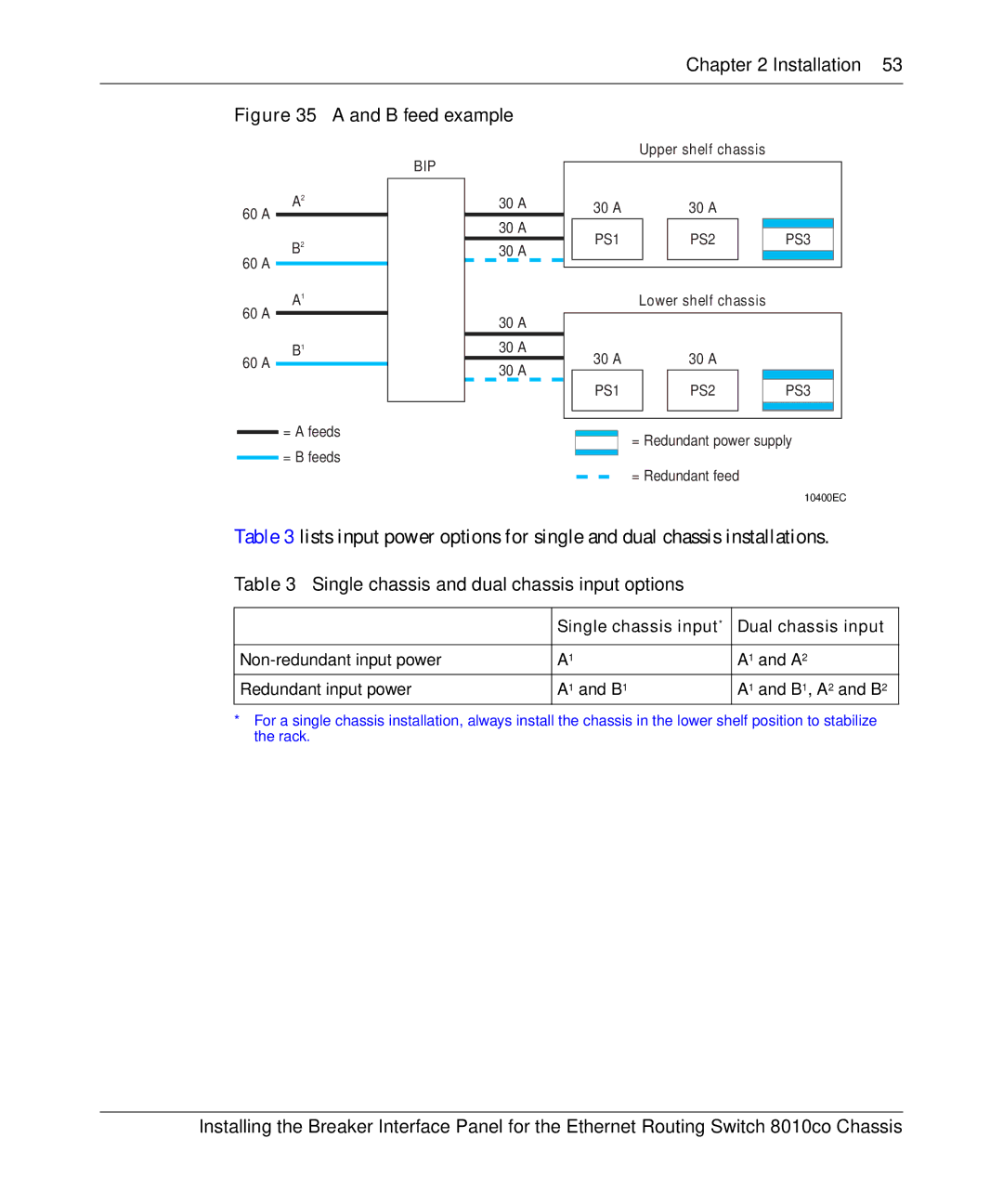
Figure 35 A and B feed example
Upper shelf chassis
A2
60 A
B2
60 A
A1
60 A
B1
60 A
=A feeds
=B feeds
BIP
30 A
30 A
30 A
30 A
30 A
30 A
| 30 A |
|
| 30 A |
|
| ||
|
|
|
|
|
|
|
|
|
|
|
|
|
|
|
|
|
|
| PS1 |
|
| PS2 |
|
| PS3 |
|
|
|
|
|
|
|
|
|
|
|
|
|
|
|
|
|
|
|
|
|
|
|
|
|
|
|
|
|
| Lower shelf chassis |
|
| ||||
|
|
|
|
|
|
|
| |
| 30 A |
|
| 30 A |
|
| ||
|
|
|
|
|
|
|
| |
|
|
|
|
|
|
|
|
|
| PS1 |
|
| PS2 |
|
| PS3 |
|
|
|
|
|
|
|
|
|
|
|
|
|
|
|
|
|
|
|
|
|
|
|
|
|
|
|
|
= Redundant power supply
= Redundant feed
10400EC
Table 3 lists input power options for single and dual chassis installations.
Table 3 Single chassis and dual chassis input options
| Single chassis input* | Dual chassis input | ||
|
|
|
|
|
A1 |
| A1 | and A2 | |
|
|
|
|
|
Redundant input power | A1 | and B1 | A1 | and B1, A2 and B2 |
*For a single chassis installation, always install the chassis in the lower shelf position to stabilize the rack.
Installing the Breaker Interface Panel for the Ethernet Routing Switch 8010co Chassis
