68Chapter 3 Problem solving
Interpreting the LEDs
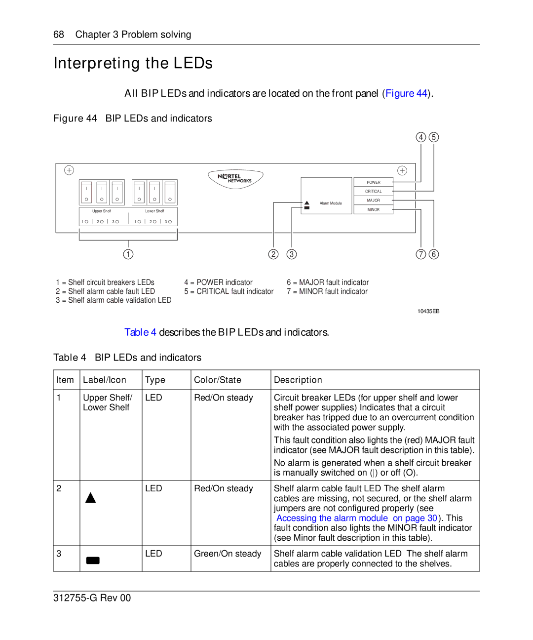
All BIP LEDs and indicators are located on the front panel (Figure 44).
Figure 44 BIP LEDs and indicators
4 5
Upper Shelf | Lower Shelf |
Alarm Module
POWER
CRITICAL
MAJOR
MINOR
1 ![]()
2 ![]()
3 ![]()
1 ![]()
2 ![]()
3 ![]()
| 1 |
| 2 | 3 | 7 | 6 | |
1 | = Shelf circuit breakers LEDs | 4 | = POWER indicator | 6 | = MAJOR fault indicator |
|
|
2 | = Shelf alarm cable fault LED | 5 | = CRITICAL fault indicator | 7 | = MINOR fault indicator |
|
|
3 | = Shelf alarm cable validation LED |
|
|
|
|
|
|
10435EB
Table 4 describes the BIP LEDs and indicators.
Table 4 BIP LEDs and indicators
Item | Label/Icon | Type | Color/State | Description |
|
|
|
|
|
1 | Upper Shelf/ | LED | Red/On steady | Circuit breaker LEDs (for upper shelf and lower |
| Lower Shelf |
|
| shelf power |
|
|
|
| breaker has tripped due to an overcurrent condition |
|
|
|
| with the associated power supply. |
|
|
|
| This fault condition also lights the (red) MAJOR fault |
|
|
|
| indicator (see MAJOR fault description in this table). |
|
|
|
| No alarm is generated when a shelf circuit breaker |
|
|
|
| is manually switched on () or off (O). |
|
|
|
|
|
2 |
| LED | Red/On steady | Shelf alarm cable fault |
|
|
|
| cables are missing, not secured, or the shelf alarm |
|
|
|
| jumpers are not configured properly (see |
|
|
|
| “Accessing the alarm module” on page 30). This |
|
|
|
| fault condition also lights the MINOR fault indicator |
|
|
|
| (see Minor fault description in this table). |
|
|
|
|
|
3 |
| LED | Green/On steady | Shelf alarm cable validation LED |
|
|
|
| cables are properly connected to the shelves. |
|
|
|
|
|
