Chapter 1 Overview 29
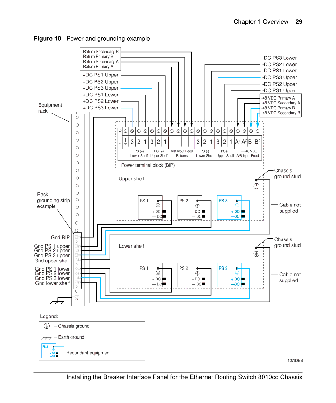
Figure 10 Power and grounding example |
| ||
| Return Secondary B |
| |
| Return Primary B | ||
| Return Secondary A | ||
| Return Primary A | ||
| |||
| +DC PS1 Upper | ||
| |||
| +DC PS2 Upper | ||
| |||
| +DC PS3 Upper | ||
| |||
| +DC PS1 Lower | ||
| |||
| +DC PS2 Lower | ||
Equipment | |||
+DC PS3 Lower | |||
rack | |||
| |||
|
| ||
| 3 2 1 3 2 1 |
| 3 2 1 3 2 1 A1 A2 B1 B2 | |||
| PS (+) | PS (+) | A/B Input Feed | PS | PS | – 48 VDC |
| Lower Shelf | Upper Shelf | Returns | Lower Shelf | Upper Shelf A/B Input Feeds | |
| Power terminal block (BIP) |
|
| Chassis | ||
|
|
|
|
|
| |
| Upper shelf |
|
|
|
| ground stud |
|
|
|
|
|
| |
Rack |
|
|
|
|
|
|
grounding strip | PS 1 |
| PS 21 |
| PS 3 | Cable not |
example |
|
|
|
|
| |
|
| + DC | + DC | + DC | supplied | |
|
| – DC | – DC | – DC |
| |
Gnd BIP |
|
|
|
|
| Chassis |
|
|
|
|
|
| |
Gnd PS 1 upper | Lower shelf |
|
|
|
| ground stud |
Gnd PS 2 upper |
|
|
|
|
|
|
Gnd PS 3 upper |
|
|
|
|
|
|
Gnd upper shelf |
|
|
|
|
|
|
Gnd PS 1 lower | PS 1 |
| PS 21 |
| PS 3 |
|
Gnd PS 2 lower |
|
|
|
|
| Cable not |
Gnd PS 3 lower |
| + DC | + DC | + DC | supplied | |
Gnd lower shelf |
| – DC | – DC | – DC | ||
|
| |||||
Legend:
= Chassis ground
= Earth ground
PS 3
+ DC |
| = Redundant equipment |
| ||
– DC |
|
|
10760EB
Installing the Breaker Interface Panel for the Ethernet Routing Switch 8010co Chassis