Chapter 2 Installation 47
Routing power supply cables to the BIP
After you connect all cables to the chassis power supplies, you must route the power supply cable leads from each chassis to the BIP. If you installed an upper and lower shelf chassis, and each chassis has three power supplies, you have 18 separate cables to route to the BIP. For this reason, Nortel recommends that you label the cables and loosely bundle and fasten them with
To route the cables to the BIP:
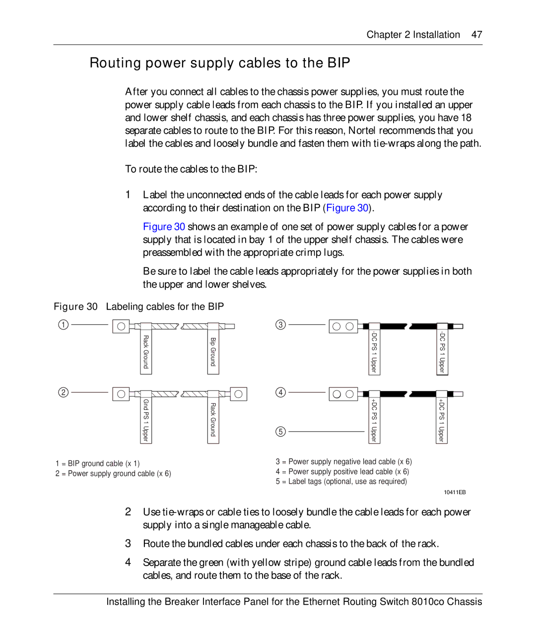
1Label the unconnected ends of the cable leads for each power supply according to their destination on the BIP (Figure 30).
Figure 30 shows an example of one set of power supply cables for a power supply that is located in bay 1 of the upper shelf chassis. The cables were preassembled with the appropriate crimp lugs.
Be sure to label the cable leads appropriately for the power supplies in both the upper and lower shelves.
Figure 30 Labeling cables for the BIP
1
Rack Ground |
| Bip Ground |
|
|
|
3
2
4 |
Gnd PS 1Upper |
| RackGround |
|
|
|
|
|
|
| +DC PS 1Upper |
| +DC PS 1Upper |
|
| 5 |
| |||||||||
|
|
|
|
|
|
|
|
|
|
| ||
|
|
|
|
|
|
|
|
|
|
|
|
|
1 = BIP ground cable (x 1)
2 = Power supply ground cable (x 6)
3 = Power supply negative lead cable (x 6)
4 = Power supply positive lead cable (x 6)
5 = Label tags (optional, use as required)
10411EB
2Use
3Route the bundled cables under each chassis to the back of the rack.
4Separate the green (with yellow stripe) ground cable leads from the bundled cables, and route them to the base of the rack.
Installing the Breaker Interface Panel for the Ethernet Routing Switch 8010co Chassis
