Chapter 1 Overview 27
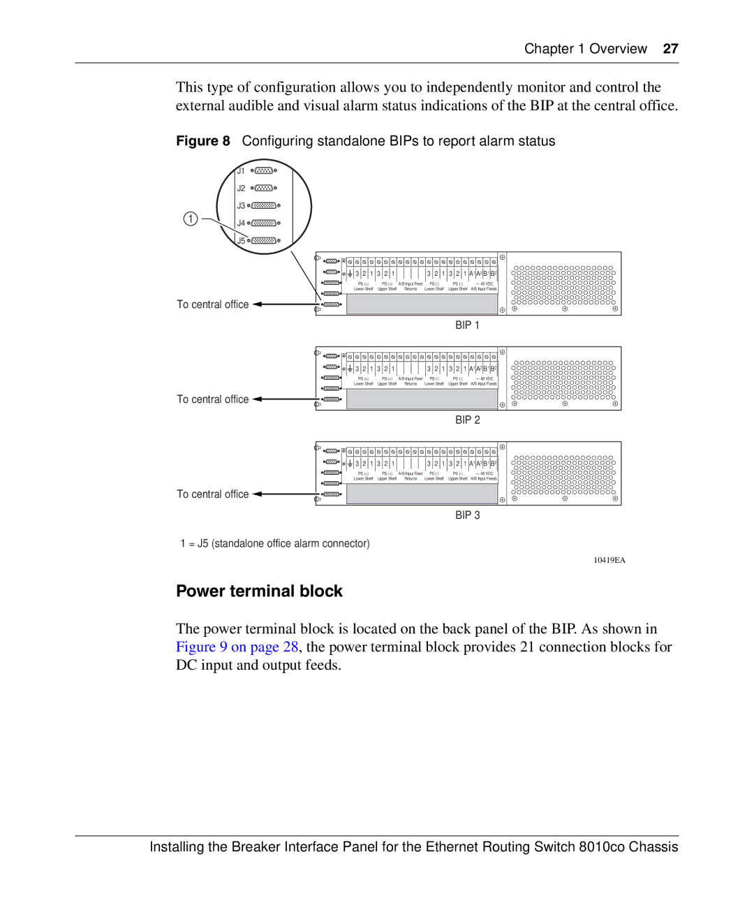
This type of configuration allows you to independently monitor and control the external audible and visual alarm status indications of the BIP at the central office.
Figure 8 Configuring standalone BIPs to report alarm status
1
J1
J2
J3 ![]()
![]()
![]()
J4 ![]()
![]()
![]()
J5 ![]()
![]()
![]()
3 2 1 3 2 1 |
| 3 2 1 3 2 1 A1 A2 B1 B2 | |||
PS (+) | PS (+) | A/B Input Feed | PS | PS | – 48 VDC |
Lower Shelf | Upper Shelf | Returns | Lower Shelf | Upper Shelf | A/B Input Feeds |
To central office |
|
|
|
|
|
|
|
|
| BIP 1 | |
3 2 1 3 2 1 |
| 3 2 1 3 2 1 A1 A2 B1 B2 | |||
PS (+) | PS (+) | A/B Input Feed | PS | PS | – 48 VDC |
Lower Shelf | Upper Shelf | Returns | Lower Shelf | Upper Shelf | A/B Input Feeds |
To central office |
BIP 2
3 2 1 3 2 1 |
| 3 2 1 3 2 1 A1 A2 B1 B2 | |||
PS (+) | PS (+) | A/B Input Feed | PS | PS | – 48 VDC |
Lower Shelf | Upper Shelf | Returns | Lower Shelf | Upper Shelf | A/B Input Feeds |
To central office |
BIP 3
1 = J5 (standalone office alarm connector)
10419EA
Power terminal block
The power terminal block is located on the back panel of the BIP. As shown in Figure 9 on page 28, the power terminal block provides 21 connection blocks for DC input and output feeds.
Installing the Breaker Interface Panel for the Ethernet Routing Switch 8010co Chassis
