Chapter 2 Installation 55
4Connect the
a Match the tagged
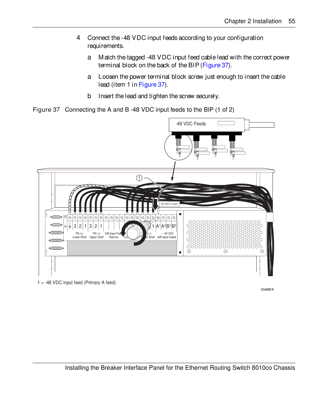
a Loosen the power terminal block screw just enough to insert the cable lead (item 1 in Figure 37).
b Insert the lead and tighten the screw securely.
Figure 37 Connecting the A and B -48 VDC input feeds to the BIP (1 of 2)
-48 VDC Feeds
|
|
|
| 1 |
|
|
|
|
|
| |
3 2 1 3 2 1 |
| 3 2 1 3 2 1 A1 A2 B1 B2 | |||
PS (+) | PS (+) | A/B Input Feed | PS | PS | – 48 VDC |
Lower Shelf | Upper Shelf | Returns | Lower Shelf | Upper Shelf | A/B Input Feeds |
1 =
10406FA
Installing the Breaker Interface Panel for the Ethernet Routing Switch 8010co Chassis