BP7360 JULIANNE 9/19/07 11:15 AM Page 6
![]()
![]()
FLAT WASHER (3) 
FAN
BLADE
BLADE FLANGE
Figure 1
![]()
![]() 2. Remove and discard the four shipping retainers securing the motor hub in the motor housing.
2. Remove and discard the four shipping retainers securing the motor hub in the motor housing.
NOTE: Take care not to scratch the fan housing when installing the blade assemblies.
![]()
![]() 3. Insert an
3. Insert an
![]()
![]() 4. Rotate the motor hub so that two threaded holes line up with the two notches in the switch cup plate (Figure 2). Position the blade flange on the motor hub so that the screws in the blades flange align with the two threaded holes in the motor hub. Loosely tighten the screws at this time. Repeat this procedure for the remaining four blade assemblies.
4. Rotate the motor hub so that two threaded holes line up with the two notches in the switch cup plate (Figure 2). Position the blade flange on the motor hub so that the screws in the blades flange align with the two threaded holes in the motor hub. Loosely tighten the screws at this time. Repeat this procedure for the remaining four blade assemblies.
![]()
![]() 5. Gently snug all flange screws to the motor hub, working around the hub in a clockwise sequence. Next, securely tighten all flange screws, again working in a clockwise sequence. Failure to follow this procedure could result in fan wobble. This completes the blade installation.
5. Gently snug all flange screws to the motor hub, working around the hub in a clockwise sequence. Next, securely tighten all flange screws, again working in a clockwise sequence. Failure to follow this procedure could result in fan wobble. This completes the blade installation.
NOTE: If you wish to assemble your ceiling fan without the lower light installed, skip steps 6 and 7, and proceed to install the switch cup assembly in accordance with steps 8 and 9.
![]()
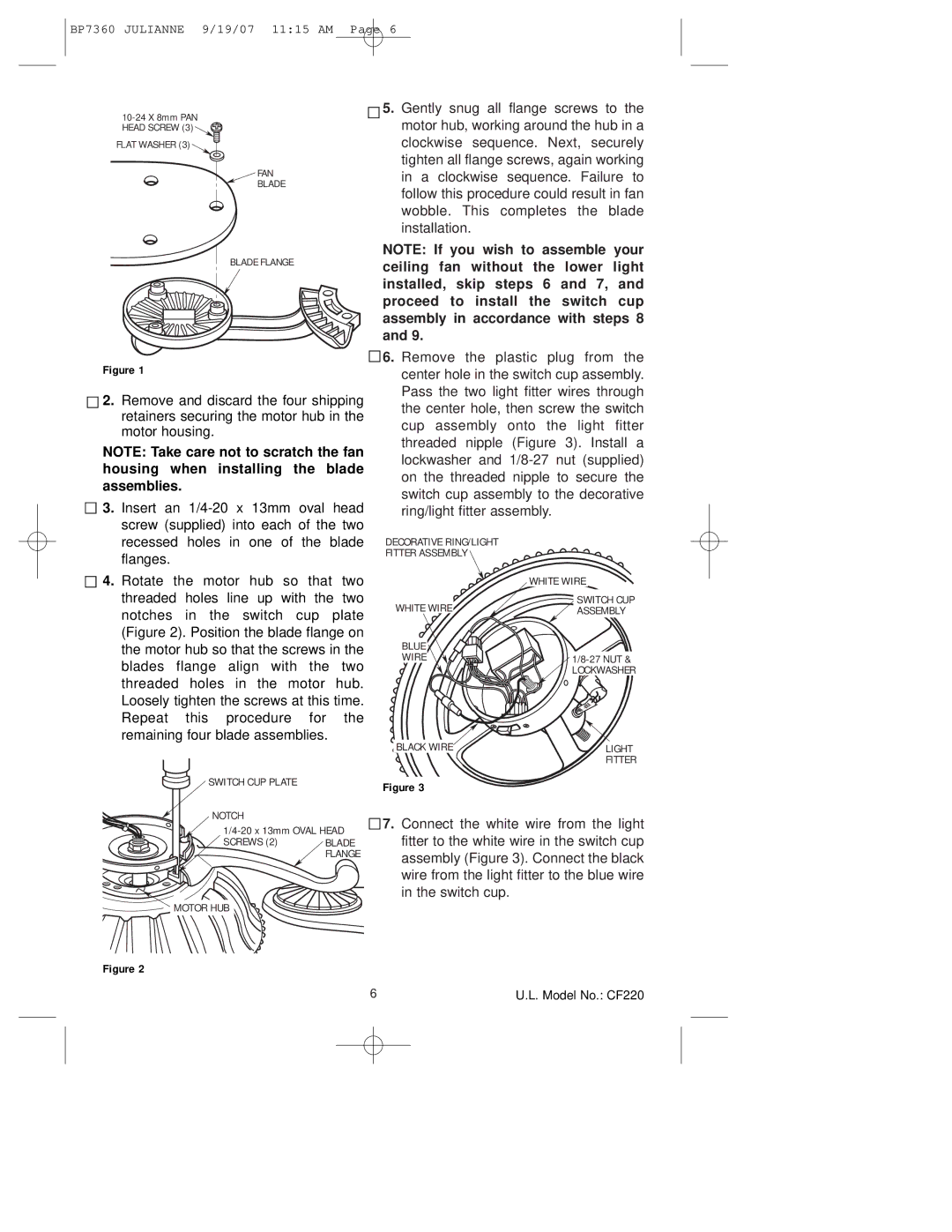
![]() 6. Remove the plastic plug from the center hole in the switch cup assembly. Pass the two light fitter wires through the center hole, then screw the switch cup assembly onto the light fitter threaded nipple (Figure 3). Install a lockwasher and
6. Remove the plastic plug from the center hole in the switch cup assembly. Pass the two light fitter wires through the center hole, then screw the switch cup assembly onto the light fitter threaded nipple (Figure 3). Install a lockwasher and
DECORATIVE RING/LIGHT
FITTER ASSEMBLY
| WHITE WIRE |
WHITE WIRE | SWITCH CUP |
ASSEMBLY |
BLUE
WIRE ![]()
![]() 1/8-27 NUT &
1/8-27 NUT &
LOCKWASHER
BLACK WIRE | LIGHT |
| FITTER |
SWITCH CUP PLATE | Figure 3 |
|
NOTCH
SCREWS (2) BLADE FLANGE
![]() MOTOR HUB
MOTOR HUB
Figure 2
![]()
![]() 7. Connect the white wire from the light fitter to the white wire in the switch cup assembly (Figure 3). Connect the black wire from the light fitter to the blue wire in the switch cup.
7. Connect the white wire from the light fitter to the white wire in the switch cup assembly (Figure 3). Connect the black wire from the light fitter to the blue wire in the switch cup.
6 | U.L. Model No.: CF220 |