BP7360 JULIANNE 9/19/07 11:15 AM Page 7
![]()
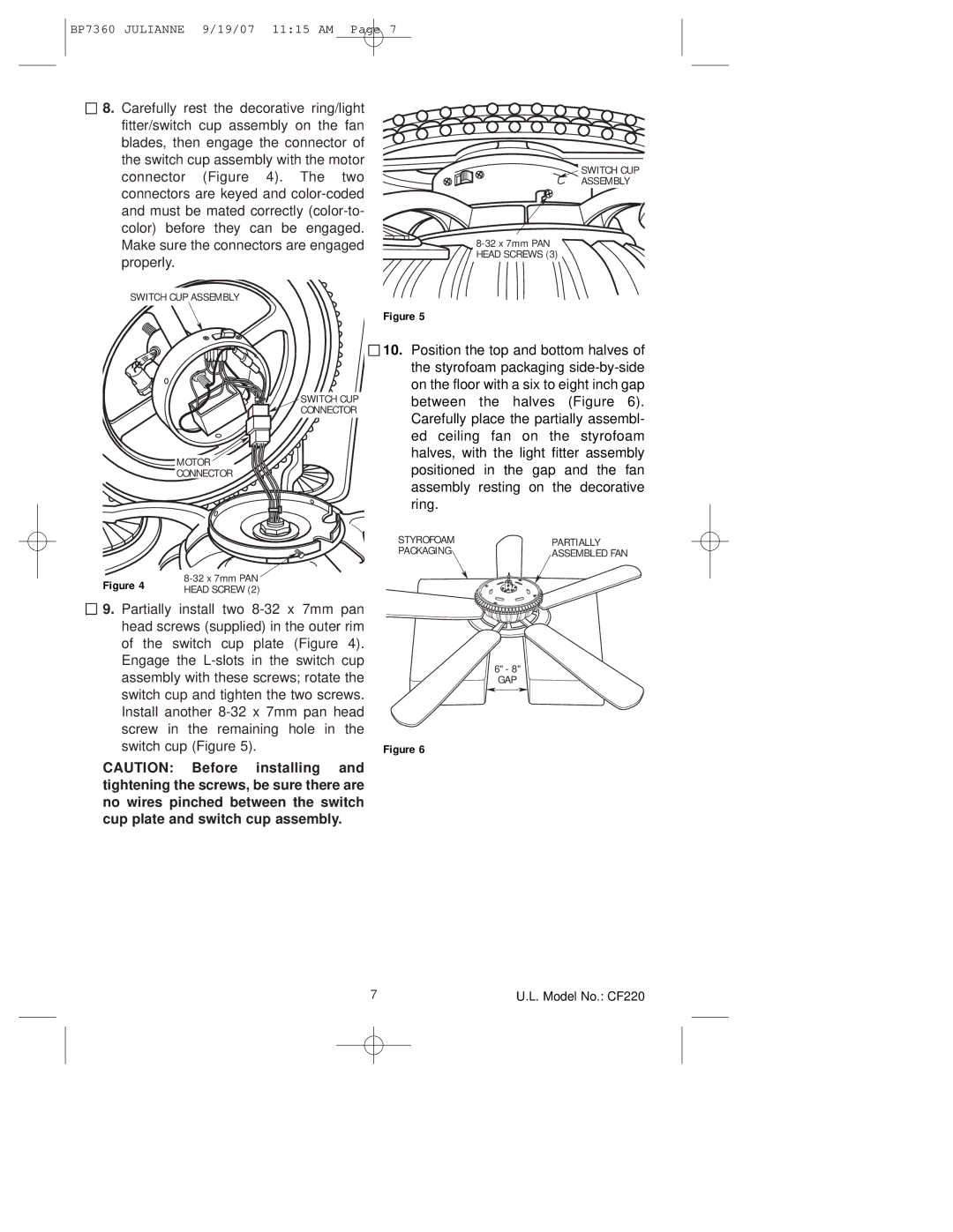
![]() 8. Carefully rest the decorative ring/light fitter/switch cup assembly on the fan blades, then engage the connector of the switch cup assembly with the motor connector (Figure 4). The two connectors are keyed and
8. Carefully rest the decorative ring/light fitter/switch cup assembly on the fan blades, then engage the connector of the switch cup assembly with the motor connector (Figure 4). The two connectors are keyed and
SWITCH CUP
ASSEMBLY
HEAD SCREWS (3) |
SWITCH CUP ASSEMBLY
Figure 5
MOTOR CONNECTOR
SWITCH CUP CONNECTOR
![]()
![]() 10. Position the top and bottom halves of the styrofoam packaging
10. Position the top and bottom halves of the styrofoam packaging
Figure 4 | |
HEAD SCREW (2) |
9.Partially install two
CAUTION: Before installing and tightening the screws, be sure there are no wires pinched between the switch cup plate and switch cup assembly.
STYROFOAM PACKAGING
Figure 6
PARTIALLY
ASSEMBLED FAN
6" - 8"
GAP
7 | U.L. Model No.: CF220 |
