Dimensional Data
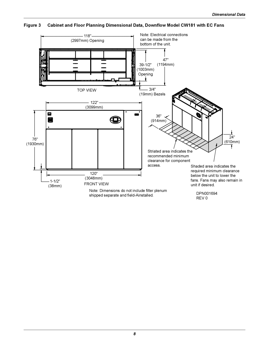
Figure 3 Cabinet and Floor Planning Dimensional Data, Downflow Model CW181 with EC Fans
|
| 118" |
|
|
|
|
|
| Note: Electrical connections | ||||||
|
|
|
|
| (2997mm) Opening |
|
|
|
| can be made from the | |||||
|
|
|
|
|
|
|
|
|
|
|
|
| bottom of the unit. | ||
|
|
|
|
|
|
|
|
|
|
|
|
|
|
|
|
|
|
|
|
|
|
|
|
|
|
|
|
|
|
|
|
|
|
|
|
|
|
|
|
|
|
|
|
|
|
|
|
| 47" |
(1194mm) | |
(1003mm) |
|
Opening |
|
76"
(1930mm)
| TOP VIEW | 3/4" |
|
|
| (19mm) Bezels |
|
| 122" |
|
|
| (3099mm) |
|
|
|
| 36" |
|
|
| (914mm) |
|
|
|
| 24" |
|
|
| (610mm) |
|
| Striated area indicates the | |
|
| recommended minimum |
|
|
| clearance for component |
|
|
| access. | Shaded area indicates the |
| 120" |
| required minimum clearance |
|
| below the unit to lower the | |
| (3048mm) |
| |
| fans. Fans may also remain in | ||
FRONT VIEW |
| ||
(38mm) |
| unit if desired. | |
Note: Dimensions do not include filter plenum
shipped separate and
8