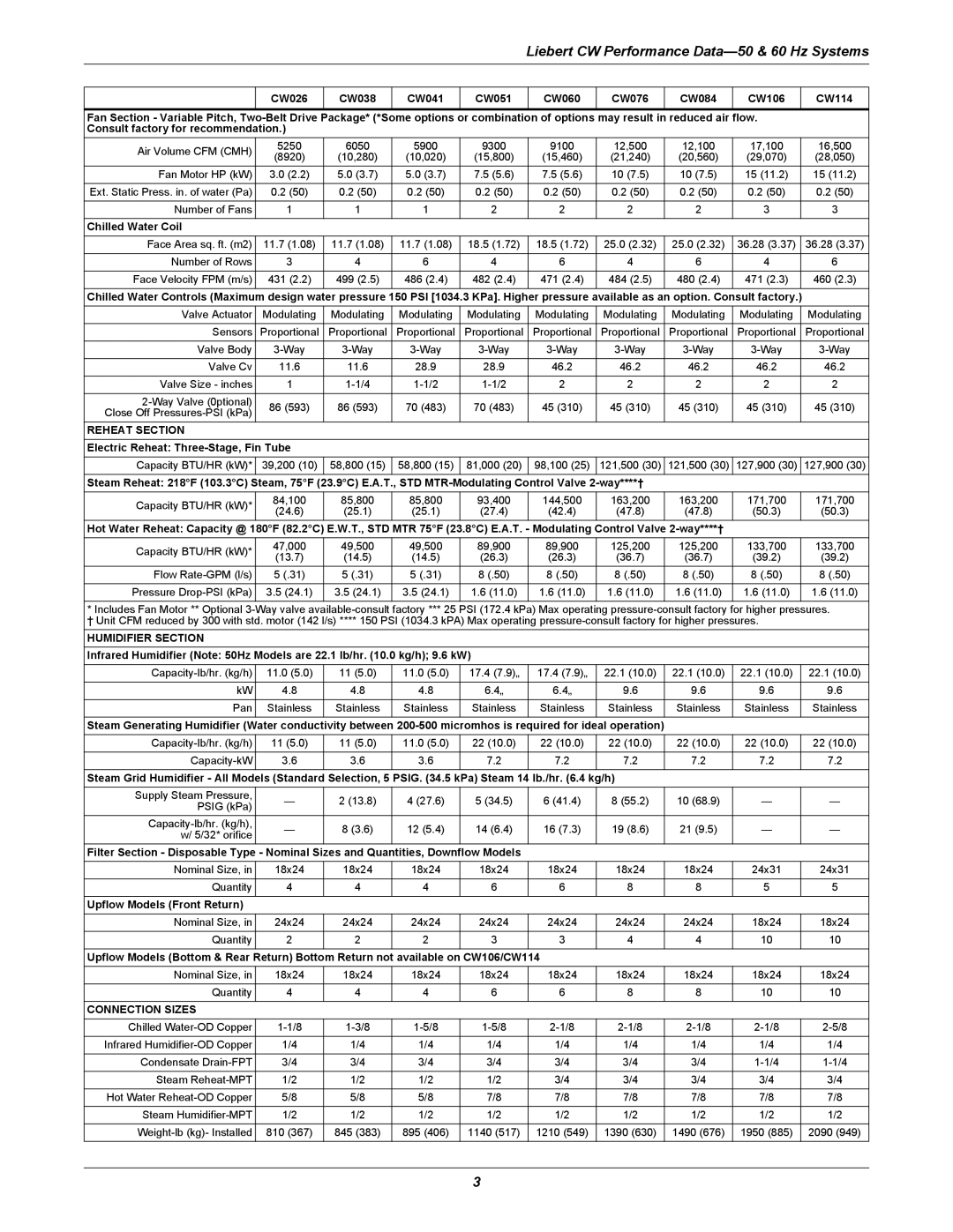
Liebert CW Performance
| CW026 | CW038 | CW041 | CW051 | CW060 | CW076 | CW084 | CW106 | CW114 | |
|
|
|
|
|
|
|
|
|
| |
Fan Section - Variable Pitch, |
| |||||||||
Consult factory for recommendation.) |
|
|
|
|
|
|
|
| ||
Air Volume CFM (CMH) | 5250 | 6050 | 5900 | 9300 | 9100 | 12,500 | 12,100 | 17,100 | 16,500 | |
(8920) | (10,280) | (10,020) | (15,800) | (15,460) | (21,240) | (20,560) | (29,070) | (28,050) | ||
| ||||||||||
Fan Motor HP (kW) | 3.0 (2.2) | 5.0 (3.7) | 5.0 (3.7) | 7.5 (5.6) | 7.5 (5.6) | 10 (7.5) | 10 (7.5) | 15 (11.2) | 15 (11.2) | |
|
|
|
|
|
|
|
|
|
| |
Ext. Static Press. in. of water (Pa) | 0.2 (50) | 0.2 (50) | 0.2 (50) | 0.2 (50) | 0.2 (50) | 0.2 (50) | 0.2 (50) | 0.2 (50) | 0.2 (50) | |
|
|
|
|
|
|
|
|
|
| |
Number of Fans | 1 | 1 | 1 | 2 | 2 | 2 | 2 | 3 | 3 | |
|
|
|
|
|
|
|
|
|
| |
Chilled Water Coil |
|
|
|
|
|
|
|
|
| |
Face Area sq. ft. (m2) | 11.7 (1.08) | 11.7 (1.08) | 11.7 (1.08) | 18.5 (1.72) | 18.5 (1.72) | 25.0 (2.32) | 25.0 (2.32) | 36.28 (3.37) | 36.28 (3.37) | |
|
|
|
|
|
|
|
|
|
| |
Number of Rows | 3 | 4 | 6 | 4 | 6 | 4 | 6 | 4 | 6 | |
|
|
|
|
|
|
|
|
|
| |
Face Velocity FPM (m/s) | 431 (2.2) | 499 (2.5) | 486 (2.4) | 482 (2.4) | 471 (2.4) | 484 (2.5) | 480 (2.4) | 471 (2.3) | 460 (2.3) | |
|
|
|
|
|
|
|
|
|
| |
Chilled Water Controls (Maximum design water pressure 150 PSI [1034.3 KPa]. Higher pressure available as an option. Consult factory.) |
| |||||||||
Valve Actuator | Modulating | Modulating | Modulating | Modulating | Modulating | Modulating | Modulating | Modulating | Modulating | |
|
|
|
|
|
|
|
|
|
| |
Sensors | Proportional | Proportional | Proportional | Proportional | Proportional | Proportional | Proportional | Proportional | Proportional | |
|
|
|
|
|
|
|
|
|
| |
Valve Body | ||||||||||
|
|
|
|
|
|
|
|
|
| |
Valve Cv | 11.6 | 11.6 | 28.9 | 28.9 | 46.2 | 46.2 | 46.2 | 46.2 | 46.2 | |
|
|
|
|
|
|
|
|
|
| |
Valve Size - inches | 1 | 2 | 2 | 2 | 2 | 2 | ||||
|
|
|
|
|
|
|
|
|
| |
86 (593) | 86 (593) | 70 (483) | 70 (483) | 45 (310) | 45 (310) | 45 (310) | 45 (310) | 45 (310) | ||
Close Off | ||||||||||
|
|
|
|
|
|
|
|
| ||
REHEAT SECTION |
|
|
|
|
|
|
|
|
| |
Electric Reheat: |
|
|
|
|
|
|
|
| ||
Capacity BTU/HR (kW)* | 39,200 (10) | 58,800 (15) | 58,800 (15) | 81,000 (20) | 98,100 (25) | 121,500 (30) | 121,500 (30) | 127,900 (30) | 127,900 (30) | |
Steam Reheat: 218°F (103.3°C) Steam, 75°F (23.9°C) E.A.T., STD |
|
|
| |||||||
Capacity BTU/HR (kW)* | 84,100 | 85,800 | 85,800 | 93,400 | 144,500 | 163,200 | 163,200 | 171,700 | 171,700 | |
(24.6) | (25.1) | (25.1) | (27.4) | (42.4) | (47.8) | (47.8) | (50.3) | (50.3) | ||
| ||||||||||
Hot Water Reheat: Capacity @ 180°F (82.2°C) E.W.T., STD MTR 75°F (23.8°C) E.A.T. - Modulating Control Valve |
|
| ||||||||
Capacity BTU/HR (kW)* | 47,000 | 49,500 | 49,500 | 89,900 | 89,900 | 125,200 | 125,200 | 133,700 | 133,700 | |
(13.7) | (14.5) | (14.5) | (26.3) | (26.3) | (36.7) | (36.7) | (39.2) | (39.2) | ||
| ||||||||||
Flow | 5 (.31) | 5 (.31) | 5 (.31) | 8 (.50) | 8 (.50) | 8 (.50) | 8 (.50) | 8 (.50) | 8 (.50) | |
|
|
|
|
|
|
|
|
|
| |
Pressure | 3.5 (24.1) | 3.5 (24.1) | 3.5 (24.1) | 1.6 (11.0) | 1.6 (11.0) | 1.6 (11.0) | 1.6 (11.0) | 1.6 (11.0) | 1.6 (11.0) | |
|
|
|
|
|
|
|
|
|
| |
* Includes Fan Motor ** Optional
† Unit CFM reduced by 300 with std. motor (142 l/s) **** 150 PSI (1034.3 kPA) Max operating
HUMIDIFIER SECTION
Infrared Humidifier (Note: 50Hz Models are 22.1 lb/hr. (10.0 kg/h); 9.6 kW)
| 11.0 (5.0) | 11 (5.0) | 11.0 (5.0) | 17.4 (7.9)„ | 17.4 (7.9)„ | 22.1 (10.0) | 22.1 (10.0) | 22.1 (10.0) | 22.1 (10.0) | |
kW | 4.8 | 4.8 | 4.8 | 6.4„ | 6.4„ | 9.6 | 9.6 | 9.6 | 9.6 | |
Pan | Stainless | Stainless | Stainless | Stainless | Stainless | Stainless | Stainless | Stainless | Stainless | |
Steam Generating Humidifier (Water conductivity between |
|
|
| |||||||
11 (5.0) | 11 (5.0) | 11.0 (5.0) | 22 (10.0) | 22 (10.0) | 22 (10.0) | 22 (10.0) | 22 (10.0) | 22 (10.0) | ||
3.6 | 3.6 | 3.6 | 7.2 | 7.2 | 7.2 | 7.2 | 7.2 | 7.2 | ||
Steam Grid Humidifier - All Models (Standard Selection, 5 PSIG. (34.5 kPa) Steam 14 lb./hr. (6.4 kg/h) |
|
|
| |||||||
Supply Steam Pressure, | — | 2 (13.8) | 4 (27.6) | 5 (34.5) | 6 (41.4) | 8 (55.2) | 10 (68.9) | — | — | |
PSIG (kPa) | ||||||||||
|
|
|
|
|
|
|
|
| ||
— | 8 (3.6) | 12 (5.4) | 14 (6.4) | 16 (7.3) | 19 (8.6) | 21 (9.5) | — | — | ||
w/ 5/32* orifice | ||||||||||
|
|
|
|
|
|
|
|
| ||
Filter Section - Disposable Type - Nominal Sizes and Quantities, Downflow Models |
|
|
|
|
| |||||
Nominal Size, in | 18x24 | 18x24 | 18x24 | 18x24 | 18x24 | 18x24 | 18x24 | 24x31 | 24x31 | |
|
|
|
|
|
|
|
|
|
| |
Quantity | 4 | 4 | 4 | 6 | 6 | 8 | 8 | 5 | 5 | |
Upflow Models (Front Return) |
|
|
|
|
|
|
|
|
| |
Nominal Size, in | 24x24 | 24x24 | 24x24 | 24x24 | 24x24 | 24x24 | 24x24 | 18x24 | 18x24 | |
Quantity | 2 | 2 | 2 | 3 | 3 | 4 | 4 | 10 | 10 | |
|
|
|
|
|
|
|
|
|
| |
Upflow Models (Bottom & Rear Return) Bottom Return not available on CW106/CW114 |
|
|
|
| ||||||
Nominal Size, in | 18x24 | 18x24 | 18x24 | 18x24 | 18x24 | 18x24 | 18x24 | 18x24 | 18x24 | |
|
|
|
|
|
|
|
|
|
| |
Quantity | 4 | 4 | 4 | 6 | 6 | 8 | 8 | 10 | 10 | |
CONNECTION SIZES |
|
|
|
|
|
|
|
|
| |
Chilled | ||||||||||
Infrared | 1/4 | 1/4 | 1/4 | 1/4 | 1/4 | 1/4 | 1/4 | 1/4 | 1/4 | |
|
|
|
|
|
|
|
|
|
| |
Condensate | 3/4 | 3/4 | 3/4 | 3/4 | 3/4 | 3/4 | 3/4 | |||
Steam | 1/2 | 1/2 | 1/2 | 1/2 | 3/4 | 3/4 | 3/4 | 3/4 | 3/4 | |
|
|
|
|
|
|
|
|
|
| |
Hot Water | 5/8 | 5/8 | 5/8 | 7/8 | 7/8 | 7/8 | 7/8 | 7/8 | 7/8 | |
Steam | 1/2 | 1/2 | 1/2 | 1/2 | 1/2 | 1/2 | 1/2 | 1/2 | 1/2 | |
|
|
|
|
|
|
|
|
|
| |
810 (367) | 845 (383) | 895 (406) | 1140 (517) | 1210 (549) | 1390 (630) | 1490 (676) | 1950 (885) | 2090 (949) | ||
3