Dimensional Data
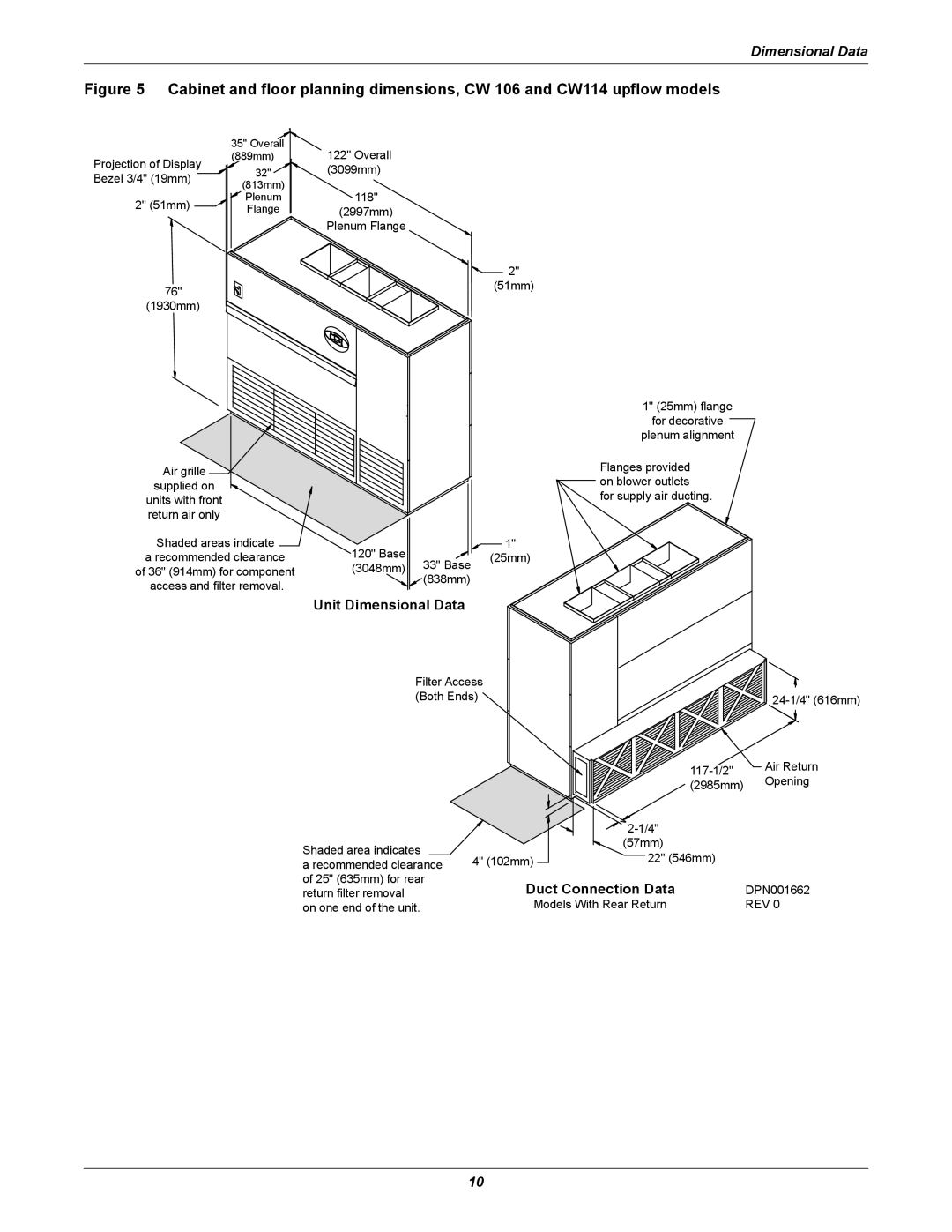
Figure 5 Cabinet and floor planning dimensions, CW 106 and CW114 upflow models
| 35" Overall | 122" Overall | |
Projection of Display | (889mm) | ||
32" | (3099mm) | ||
Bezel 3/4" (19mm) | |||
(813mm) |
| ||
| 118" | ||
2" (51mm) | Plenum | ||
Flange | (2997mm) | ||
| |||
|
| Plenum Flange | |
76" |
|
| |
(1930mm) |
|
|
![]()
![]() 2" (51mm)
2" (51mm)
1" (25mm) flange
for decorative
plenum alignment
Air grille supplied on ![]()
units with front return air only
Shaded areas indicate
a recommended clearance of 36" (914mm) for component access and filter removal.
120" Base
(3048mm) 33" Base
![]()
![]() (838mm)
(838mm)
Flanges provided on blower outlets for supply air ducting.
![]() 1" (25mm)
1" (25mm)
Unit Dimensional Data
Filter Access |
|
| |
(Both Ends) |
| ||
|
| Air Return | |
|
| Opening | |
|
| (2985mm) | |
|
|
| |
|
|
| |
Shaded area indicates |
| (57mm) |
|
4" (102mm) | 22" (546mm) |
| |
a recommended clearance |
| ||
of 25" (635mm) for rear | Duct Connection Data | DPN001662 | |
return filter removal | |||
on one end of the unit. |
| Models With Rear Return | REV 0 |
10