Installation and Configuration
The adjustable
To install the rack mount brackets:
1.Unpack two (2)
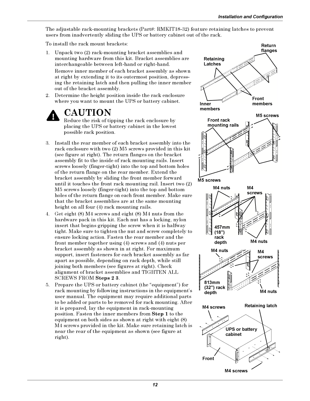
Remove inner member of each bracket assembly as shown at right by extending it to its outermost position, depress- ing the retaining latch and then pulling the inner member out of the bracket assembly.
2.Determine the height position inside the rack enclosure where you want to mount the UPS or battery cabinet.
! CAUTION
Reduce the risk of tipping the rack enclosure by placing the UPS or battery cabinet in the lowest possible rack position.
3. Install the rear member of each bracket assembly into the |
rack enclosure with two (2) M5 screws provided in this kit |
(see figure at right). The return flanges on the bracket |
assembly fit to the inside of rack mounting rails. Insert |
screws loosely |
of the return flange on the rear member. Extend the |
bracket assembly by sliding the front member forward |
until it touches the front rack mounting rail. Insert two (2) |
M5 screws loosely |
holes of the return flange on each front member. Make sure |
that the bracket assemblies are at the same mounting |
height on all four (4) rack mounting rails. |
4. Get eight (8) M4 screws and eight (8) M4 nuts from the |
hardware pack in this kit. Each nut has a locking, nylon |
insert that begins gripping the screw when it is halfway |
tight. Make sure to tighten the nut and screw completely to |
ensure locking action. Fasten the rear member and the |
front member together using (4) screws and (4) nuts per |
bracket assembly as shown in at right. For maximum |
support, insert fasteners for each bracket assembly as far |
apart as possible, depending on rack depth, while still |
joining both members (see figures at right). Check |
alignment of bracket assemblies and TIGHTEN ALL |
SCREWS FROM Steps 2 3. |
Retaining
Latches
Inner members
Front rack mounting rails
M5 screws
M4 nuts
457mm
(18") rack depth
M4 nuts
Return flanges
Front members
M5 screws
M4 screws
M4 nuts
M4 screws
5. Prepare the UPS or battery cabinet (the “equipment”) for |
rack mounting by following instructions in the equipment’s |
user manual. The equipment may require additional parts |
to be added or parts to be removed for rack mounting. After |
it is prepared, lay the equipment in |
position. Fasten the inner members from Step 1 to the |
equipment on both sides as shown at right with eight (8) |
M4 screws provided in the kit. Make sure retaining latch is |
near the rear of the equipment as shown (see figure at |
right). |
813mm |
|
(32") rack | M4 nuts |
depth | |
M4 screws | Retaining latch |
| UPS or battery |
| cabinet |
Front
M4 screws
12