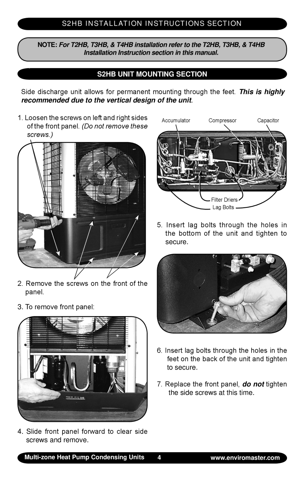
S2HB, T2HB, T3HB, T4HB specifications
The EMI T4HB, T3HB, T2HB, and S2HB models represent innovative advancements in the field of electronic security and surveillance technology. Each model is designed to meet specific security needs while integrating cutting-edge features, making them suitable for a variety of applications, from residential monitoring to large-scale facility management.Starting with the T4HB, this model is known for its high-definition video capabilities and robust build quality. It offers 4K resolution, providing crystal-clear image quality that captures fine details, making it easier to identify subjects. The T4HB is equipped with advanced night vision technology, allowing it to perform optimally in low light conditions. Additionally, it features motion detection and smart analytics that minimize false alarms and provide users with real-time alerts. The integration with cloud storage solutions ensures that footage is securely saved and easily accessible from various devices.
The T3HB is a slightly scaled-back version, yet it does not compromise on essential features. It supports 1080p full HD resolution and incorporates many of the same intelligent analytics capabilities as its T4HB counterpart. With a wide-angle lens, the T3HB allows coverage of larger areas with fewer cameras. Its weather-resistant design makes it suitable for both indoor and outdoor installations, protecting it from the elements and ensuring reliable performance.
Next is the T2HB, which balances performance and affordability. This model retains high-definition video quality and basic motion detection features, making it ideal for budget-conscious consumers who still want reliable surveillance. The T2HB focuses on user-friendliness with simple setup processes and mobile app integration that allows for easy remote monitoring, making it an attractive option for homeowners.
Lastly, the S2HB is engineered for versatility. It combines the advantages of all previous models, providing excellent video quality and configurable settings for personalized security needs. The S2HB stands out with its smart home compatibility, enabling integration with various smart devices in a home security ecosystem. Its compact design allows for flexible mounting options without compromising performance.
Together, the EMI T4HB, T3HB, T2HB, and S2HB models reflect a commitment to quality, innovation, and user satisfaction in the modern security landscape. They cater to various needs, ensuring that users can find a suitable solution for their surveillance requirements while benefiting from advanced technologies that enhance security and peace of mind.

