Installation
9.Connect the wires in the stove.
10.Set the Slider Damper as described in the INSTALLATION - SLIDER/DAMPER SETTING“ section.
NOTE:
Ensure that all vent connections are installed by placing three (3) screws evenly spaced and a small bead of high temperature silicone at each chimney connection. Also ensure that all vertical vent sections are properly supported and that all clearances to combustibles are maintained in accordance with the vent manufacturer’s specifications.
Vent termination cap
Siding
(stainless steel termination
hood) or 45° elbow with
rodent screen
Wall strap
(recommended with
use of vent pipe)
Vent pipe or 610mm ![]() (2 foot) riser
(2 foot) riser
Pipe adapter (if using riser)
Exterior blower ![]() and housing
and housing
Horizontal frame ![]()
![]() for thimble
for thimble
Armour cable supplying power to exterior blower
90° elbow
Wall framing
Wall thimble
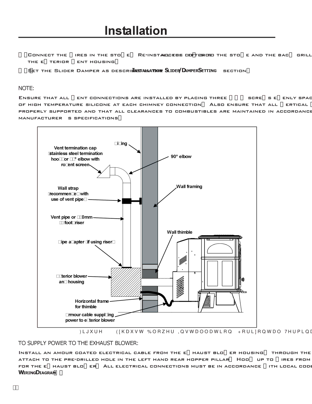
Figure 19: Exhaust Blower Installation; Horizontal Termination.
TO SUPPLY POWER TO THE EXHAUST BLOWER:
Install an amour coated electrical cable from the exhaust blower housing, through the wall thimble, and attach to the
WIRING DIAGRAM).
18
