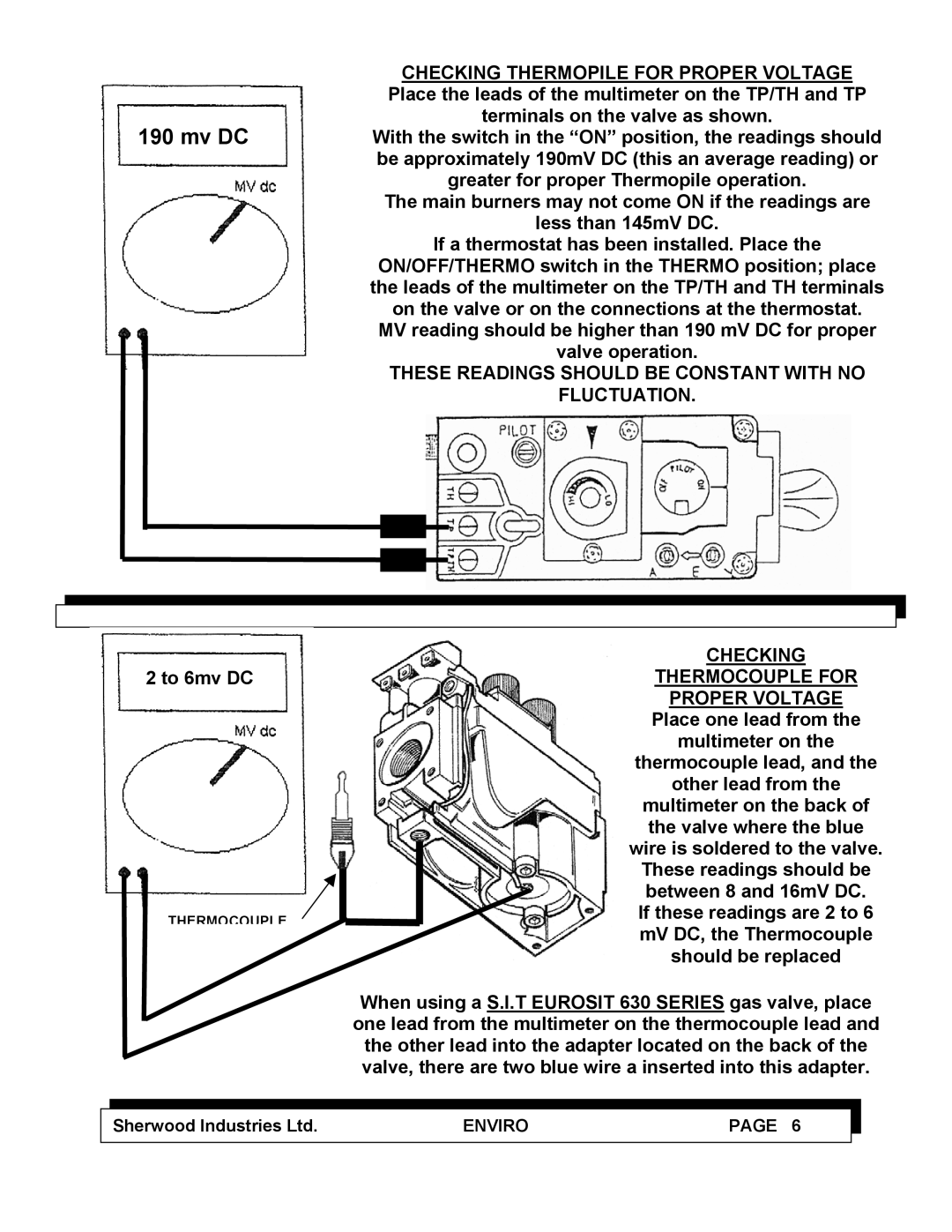
CHECKING THERMOPILE FOR PROPER VOLTAGE Place the leads of the multimeter on the TP/TH and TP terminals on the valve as shown.
190 mv DCWith the switch in the “ON” position, the readings should be approximately 190mV DC (this an average reading) or
greater for proper Thermopile operation.
The main burners may not come ON if the readings are
less than 145mV DC.
If a thermostat has been installed. Place the
ON/OFF/THERMO switch in the THERMO position; place the leads of the multimeter on the TP/TH and TH terminals on the valve or on the connections at the thermostat. MV reading should be higher than 190 mV DC for proper valve operation.
THESE READINGS SHOULD BE CONSTANT WITH NO
FLUCTUATION.
|
|
|
| CHECKING |
|
|
|
| |
2 to 6mv DC |
|
| THERMOCOUPLE FOR | |
|
|
|
| PROPER VOLTAGE |
|
|
|
| Place one lead from the |
|
|
|
| multimeter on the |
|
|
|
| thermocouple lead, and the |
|
|
|
| other lead from the |
|
|
|
| multimeter on the back of |
|
|
|
| the valve where the blue |
|
|
|
| wire is soldered to the valve. |
|
|
|
| These readings should be |
|
|
|
| between 8 and 16mV DC. |
|
|
|
| If these readings are 2 to 6 |
| THERMOCOUPLE |
| ||
|
| mV DC, the Thermocouple | ||
|
|
|
| |
|
|
|
| should be replaced |
|
|
|
|
|
|
|
|
| When using a S.I.T EUROSIT 630 SERIES gas valve, place |
|
|
|
| one lead from the multimeter on the thermocouple lead and |
|
|
|
| the other lead into the adapter located on the back of the |
|
|
|
| valve, there are two blue wire a inserted into this adapter. |
|
|
|
|
|
|
|
|
|
|
| Sherwood Industries Ltd. | ENVIRO | PAGE 6 |
|
|
|
|
|
|
